This procedure is for troubleshooting a system exhibiting CFC
related failures, identified by either physical inspection of a fan
not working or an error message in the GE Syslog. There are two separate
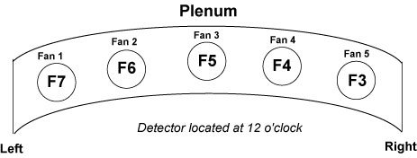
CFC’s. The rotating CFC controls the five fans in the detector
plenum, meanwhile, the stationary CFC controls the fans on the top
covers and the heater blower fan. See CFC Physical Identification for physical Identification of fans.
Both VCT and HD CFC’s use the same snap-in fuses which
are replaceable. However, some VCT systems may have an older CFC
model with non-replaceable soldered-in fuses. This model can be identified
by the Molex connectors, See Figure 5. The fuse replacement is only
for CFC with the following Part No’s: 5141497, 5141494-2,
5141497-3 and 5195573.
2 CFC Physical Identification
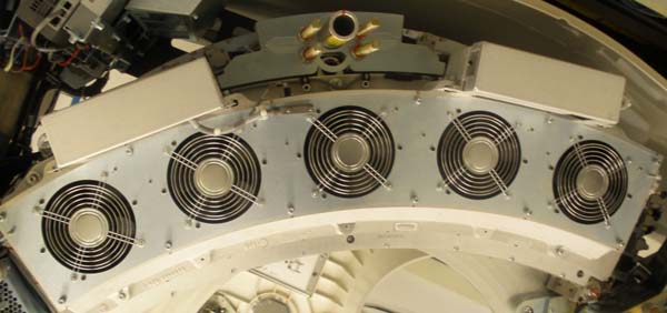
Figure 1. Rotating CFC with cable safety covers.
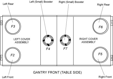
Figure 2. Rotating Plenum Fans
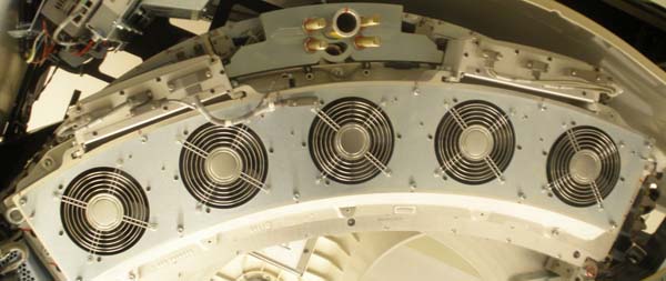
Figure 3. Rotating CFC with cable covers removed.
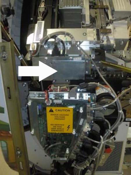
Figure 4. Stationary CFC
Figure 5. Non-repairable CFC with Molex Connectors
(Part No. 5113960)
note:
Fuse replacement is not possible with the Molex Style
CFC. If failure occurs, replace the entire CFC assembly.
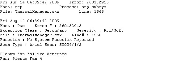
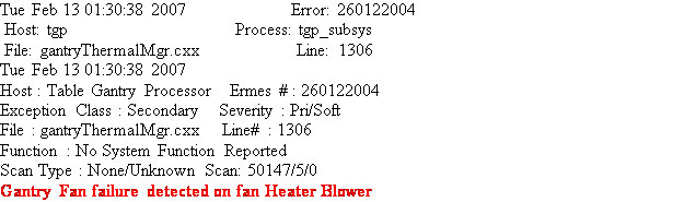
3 GE Syslog Error Message
Figure 6.
Plenum Fan Failure Error Message - Fan 4
Figure 7. Gantry Stationary Fan Failure Error Message
4 CFC Troubleshooting
Check the GE Syslog for a Fan failure message. Follow the steps
for your fan type below.
4.1 Rotating Fan Failure
Remove Gantry Side, Top and Front Covers.
Turn off [120VAC], [HVDC ENABLE] and
[AXIAL DRIVE ENABLE] switches on the Service Switch Panel
Locate rotating CFC and remove the
CFC safety cover. There are four 3mm Hex screws, remove the two on
top and loosen the two on bottom.
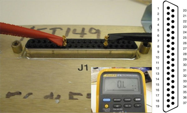
Remove J1 connector on CFC.
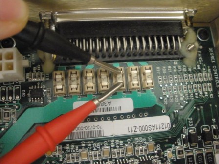
Use a multi-meter and sub-D pins to
measure Resistance across the corresponding fuse on the J1 connector
(See Figure 8) Refer to Table 1 for CFC Fuse pinout.
note:
Measuring an Open circuit or open loop indicates a blown
fuse. Measuring the fuse through the circuit, J1, typically a good
circuit measures greater than 100kOhms.
Figure 8. Fuse Test on Rotating CFC with J1 Illustration
This illustration indicates open loop with “O.L”
on Fluke 87.
If a fuse is bad, remove CFC Assembly from Detector Plenum held by six 6mm Hex nuts.
Open the CFC Cover held by six 2.5mm Hex nuts. find and replace the
blown fuse. See Table 1for identification and for Table 2 FRU list.
If the fuse is good, order a new CFC
Assembly and replace. Refer to procedure: Replacement > Gantry>
DAS and Detector > Heater Controller and Fan Controller Replacement
Re-install the CFC, reconnect the CFC
Cables and return system to original condition.
Turn gantry and console ON. Inspect the fans to see if they are working. Check
the GE Syslog for a Fan Failure message.
4.2 Stationary Fan Failure
Remove Gantry side and top covers.
Figure 9. Stationary Fans Top View
Turn off 120VAC, HVDC ENABLE, and AXIAL DRIVE
ENABLE switches.
Locate Stationary CFC Assembly (Left
side) and remove stationary CFC cover. See Figure 4.
Use a multi-meter to measure Resistance
across the corresponding fuse. See Figure 10. For Fuse location refer to Table 1.
Figure 10. Fuse Test on Stationary Side
note:
Measuring an Open circuit or open loop indicates a blown
fuse. (Figure 8 indicates open loop with “O.L” on Fluke
87). Measuring the fuse through the circuit, J1, typically a good
circuit measures greater than 100kOhms.
If the fuse is bad, replace the blown fuse. See Table 1for identification and Table 2 for FRU part.
If the fuse is good, order a new CFC
assembly and replace. For replacement procedure see: Replacement>Gantry>DAS
and Detector>Heater Controller and Fan Controller Replacement.
Re-install the CFC, re-connect CFC
cables and return system to original condition.
Turn gantry and console ON. Inspect the fans to verify they are operational.
Check the GE Syslog for fan failure message.

 note:
note: