- Topic ID: id_15460628
- Version: 2.0
- Date: Nov 8, 2018 1:36:20 AM
Verify Site Readiness
1 A1 Breaker
 |
|
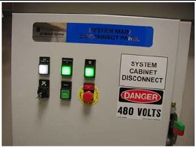
Lock-out and tag-out the A1 breaker now.
Figure 1. Sample A1 Breaker
2 Installation Support Kits
VCT-5133492
A new LightSpeed VCT Installation Support Kit is shipped in the lean install cart located in a top tray. Locate this box now and open it. All included materials are used during the installation process. Leave these items ON site.
Locate the install packet from the PMI. It contains:
-
Room Print
-
Contact names
-
Copy of the Site changes or deviations
3 Installation Conditions
-
A Final Site Print is required. Contact your PMI for a final site print.
-
The room size must match the print.
Measure the room size. If it does not match the stated size, and is smaller, then check all clearances. Service clearances MUST be met to continue.
-
A customer Anchoring Plan is required if there is anything other than a 101.6 mm (4 in.) (minimum) concrete floor. GE employees shall only install the anchors supplied with this system.
-
Complete this section on the GE Form e4879.
-
Do not start the installation process if the site is under construction:
-
In the room
-
In the scan area
-
In addition, the radiology suite at such a site will REMAIN in a dust-free, occupancy-ready state after delivery and throughout the remaining construction phase.
-
4 Floor Preparation
4.1 Preparation
The PMI notifies the installation team if any requirements are not met. It is the purchaser’s (buyer) responsibility to provide an approved support structure and an approved method of mounting. General Electric is not responsible for any failure of the support structure or method of anchoring.
4.2 Flooring
The system has a total floor load of approximately 3021 kg (6660 lbs). A concentrated load of about 2291 kg (5050 lbs), including patient (227 kg (500 lbs)) is found in the table-gantry assembly. For more information, refer to the Pre-installation Manual for this system.
Do not place the scanner on any resilient flooring. Resilient tile or carpeting may slowly yield over a period of time and disturb the alignment of the table to the gantry. Refer to the floor template to determine locations where resilient flooring material should be removed.
Limitations include:
-
No part of the floor surface within the table, gantry, or the two interface areas between table and gantry should be higher than the support areas for the table and gantry.
-
The floor structure must withstand the occupied weight of table and gantry, as well as the individual contact area loading of these components.
-
The method and placement of anchors or through bolts must not reduce the structural strength of the floor.
-
In some circumstances, the final floor may not be installed. Refer to Chapter 8.0 in the Pre- Installation Manual for this system.
If you have to remove the gantry covers in order to move the gantry into the room, refer to the cover removal procedure. Please read the notice statement in Gantry Front Cover Removal before removing the gantry covers.
5 Room Preparation
-
Use the GE print developed for your site to establish the room layout. Make sure all the operating and service clearances shown on the print are observed. Record this information on the GE Form e4879.
-
Clean the area. The mounting surface must be free of any material that may interfere with the positioning and leveling of the system.
-
Measure and determine ISO using the GE Site print. Using a marker, mark ISO on the floor. Use a chalk line to connect the table center line marks on the floor. This is the line on the print that runs down the center of the table through the gantry. Use this as a reference when positioning the table.