- Topic ID: id_15460674
- Version: 3.0
- Date: Sep 30, 2019 9:25:58 PM
VeRB2 Theory
1 Volume Reconstruction Box - Version 2 (VeRB2) Computer Overview
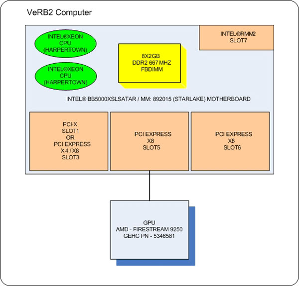
Figure 1. VeRB2 Computer
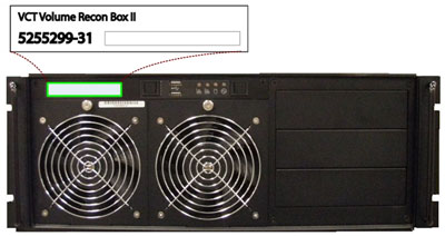
The Volume Reconstruction Box Computer Version 2 (VeRB2) used in the Global Operator Console Series (GOC 6.5) is a custom designed computer based on the Intel x86 multi-core processor server platform and manufactured by a third party vendor for GE Healthcare.
 (Also Note: The VeRB2 Computer utilized in a VCT System may also be referred to as a VVRB)
The VeRB2 is utilized for performing Adaptive Statistical Iterative Reconstruction (ASiR) function. In addition the VeRB2 Computer enhances the RECON Engine's Image Generation Frame Rate performance.
The VeRB2 Computer communicates with the Host Computer through the Console Network Switch (CNS) and is remotely booted through this connection. Once operational the VeRB2 Computer performs reconstruction processes controlled by Host Software Subsystem.
Figure 2. VeRB2 Computer (Rear)
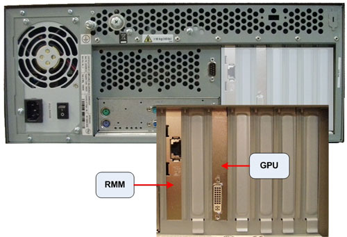
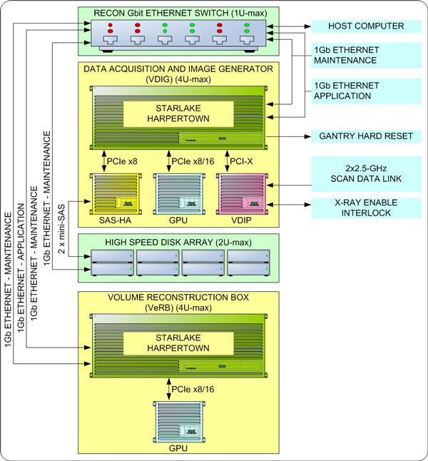
Figure 3. VeRB2 Interconnect Diagram
The following is a brief theory overview of the hardware and software associated with the VeRB2 Computer.
2 VeRB2 Computer Hardware
The VeRB2 Computer is a two (2) Quad-Core Intel® Xeon® processor (Harpertown) based computer configured by GE Healthcare utilizing the Intel Starlake (S5000XSL) server class board.
Basic Configuration:
-
1- Intel® Starlake (S5000XSL) server class motherboard
-
8 - 2 GB, DDR2 ECC 667MHz PC5300 DIMM Memory Modules (total of 16 GB)
-
1 - AMD® Firestream™ 9250 GPU Card
-
1 - 400 Watt PSU
Figure 4. VeRB2 Computer Block Diagram
2.1 Motherboard
The motherboard contained in the VeRB2 Computer utilizes the following integrated hardware.
Dual LGA Socket J (771-pin LGA) Multi-core Intel® Xeon® Processor Motherboard with:
-
• 2 Intel® Quad-core Zeon® (Harpertown) 2.33 GHz Processors with 4 MB shared L2 Cache
-
• Front Speed Buss of 1333 MHz
-
• 8 Memory Slots (32 GB max.)
-
• Integrated
-
Video
-
2 x GBit NIC Ports
-
USB 2.0 Ports
-
SATA Hard Disk Controller (Not used)
-
-
• Remote Management Module (RMM)
http://support.intel.com
Complete details of the Intel® Starlake (S5000XSL) server class motherboard can be obtained from the at the Intel® support web site.
See the following illustrations for Motherboard Layout.
Figure 5. Intel® Starlake Motherboard Layout
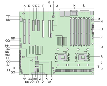
Figure 6. Intel® Starlake ATX I/O Layout
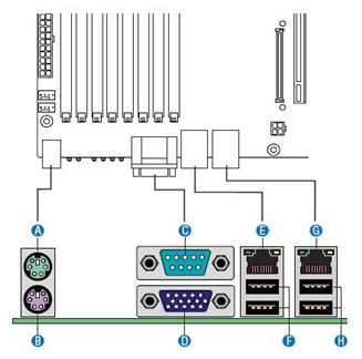
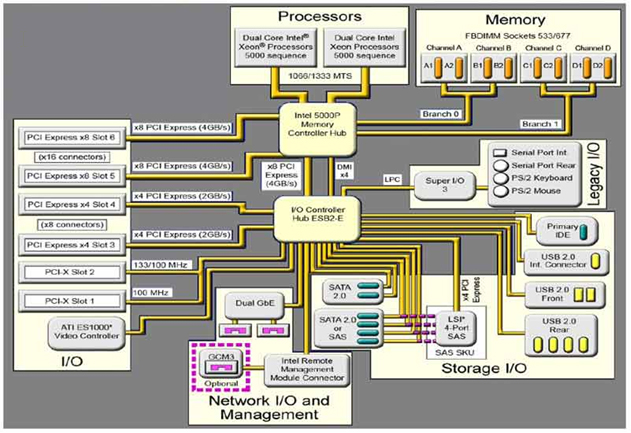
Figure 7. Intel® Starlake Motherboard Block Diagram
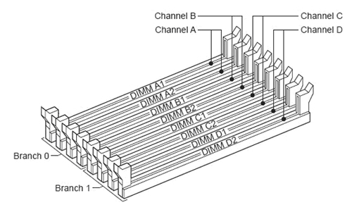
2.1.1 Memory Modules
The VeRB2 Computer is equipped to handle up to eight (8) fully buffered DIMM Memory Modules.
The base memory configuration contains eight (8) two (2) GB, DDR2 ECC 667MHz PC5300 DIMM Memory Modules (total of 16 GB).
See the following illustration for Memory Slot Assignment.
Figure 8. Memory Slot Assignment
2.1.2 Integrated Network Interface Controller (NIC)
An integrated Dual Gbit Ethernet controller on the VeRB2 motherboard handles network interface support for the VeRB2 computer. Each network interface controller (NIC) drives two LEDs located on each network interface connector. The Link/Activity LED at the left of the connector indicates connection when on, and transmit / receive activity when blinking. The Speed LED at the right of the connector indicates data rate. See the following illustration for NIC LED status.
Figure 9. NIC Status LEDs

2.2 GPU Card - AMD® Firestream™ 9250
The AMG Firestream Graphics Processor card is the main image reconstruction processor in the GRE subsystem and supplies the same functionality as the RAC boards in previous generation of the GOC consoles. The Firestream 9250 card utilizes the RV770 GPU which is specifically designed to handle highly parallel computation, needed for image generation and reconstruction.
Firestream 9250 GPU specifications:
-
Second generation AMD GPU with DP-FP in hardware
-
1GB on-board GDDR3 memory
-
Fits in one full-length, single slot with one open PCIe 2.0, x16 slot
2.3 Power Supply (PSU)
The VeRB2 Computer is powered by a 400 Watts PSU. Rated voltage range 95–132 VAC and line frequency 50–60 (+/- 3) Hz, auto switching and power factor correction.
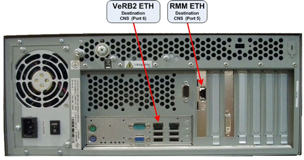
3 VeRB2 COMPUTER CONNECTIONS
See the following illustration for Connection Labeling of the VeRB2 Computer in the GOC 6.5 console.
Figure 10. VeRB2 Computer Connections
4 VeRB2 Computer Software
4.1 VeRB2 Computer Operating System (OS) and Application (APPS) System Software
The VeRB2 OS and Application software is located on a dedicated Network File System (NFS) on the Host Computer hard drive. Upon successful POST of the VeRB2 Computer hardware, the VeRB2 remote boots from this dedicated Network File System (NFS) and loads the operation software to VeRB2’s memory. The VeRB2 Computer runs on a specifically configured GE Healthcare Linux OS and Application software, found on the Host Computer Operating Disk (/usr/g/verb).
4.2 VeRB2 Computer BIOS Software
The VeRB2 Computer is equipped with a ROM-based initialization firmware that starts the server hardware. The BIOS of the computer is a collection of machine language programs stored as firmware in ROM. The BIOS ROM includes such functions as POST, PCI device initialization, Plug 'n Play support, power management activities, and the Computer Setup Utility.