- Topic ID: id_15460282
- Version: 2.0
- Date: Nov 8, 2018 1:36:46 AM
VCT Liquid Bearing Tube Rotor Control Thermal Guidance for Hot landing prevention
Introduction
On VCT systems with Liquid Bearing Tubes (LBT), special precautions must be followed when performing service on a system. This module will review four special circumstances Service Personnel should be aware of when providing service.
-
Heat exchanger cooling circuit: Fix heat exchanger and pump cooling circuit issues prior to any ball bearing or liquid bearing tube installation (Errors 260118275 and 260118260).
-
Tube temperature: Verify tube temperature is in recommended TubeCare temperature zone before rotor stop procedures.
Check Tube temperature for determining temperature when supporting customers by the following way.
-
Execute rotor_ctrl -temp command.
-
Check tubeTemp.csv log.
-
-
Tube rotor status: Check rotor status prior to performing any service procedures.
-
System operation: Use proper system operation and recommended tube cooling.
1 Heat exchanger cooling circuit
It is essential to fix any heat exchanger and pump cooling circuit issues prior to the installation of ball bearing and liquid bearing tubes. The following errors are indications of a faulty cooling circuit and are safety switches that need resolution when they occur. Follow PSDB instructions for resolution.
-
Error: 260118275 (110-0903) Tube casing temperature has exceeded 92 degree C.
-
Error: 260118260 (80-1422) Overpressure or Blown fuse.
2 Tube temperature
-
Check tube temperature before performing a system shutdown, a system restart, or any service procedures.
Only stop the rotor in blue or yellow TubeCare zones.
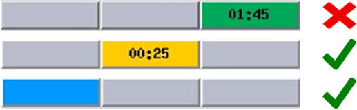 note:
note:Time remaining in a given zone is shown in that box.
-
For remote service use the following methods to check tube temperature:
-
Use rotor_ctrl -temp command to show current Tube temperature.
-
Check /usr/g/service/log/tubeTemp.csv for the Tube temperature logged every 1 minute. Find the latest temperature.
If below <210C and a subsequent check shows a decreasing temperature it is ok to stop the rotor. If it is above 210C wait until the tube temperature is <210C to stop the rotor.
note:This is posted every 1 minute until the tube temperature falls below 118C. If there is no temperature posted other than the first one after software initialization it means the tube temperature is below 118C.
-
3 Tube rotor status
-
Check rotor status before performing any of the following procedures that stop the rotor.
In tool:
-
rotor_ctrl –stop (command line tool)
-
DAS tools: following submenus.
Auto test, Manual tests, Power off
-
Diagnostic Data Collection: following submenus.
Static or Rotating X-Ray Off: Rotor Override - default/off
-
System Reset – Scan
-
Restore System State of Characterization.
-
KV Diagnostics: following submenus.
Inverter Short Circuit, Inverter Gate Command, Heater Diagnostics, Fan Diagnostics, Rotor Diagnostics, Meter Verification, No Load kV, Initialize Database, Save & Restore Runtime Parameters
Out of tool:
-
A1 panel off with System shutdown
-
HVDC switch off at Gantry Service switch panel
-
Gantry Balance tool
-
FRDM Wizard tool
-
FLASH Download tool
-
Application shutdown / Application restart through “st” command
note:A HVBAT data pull does not stop the rotor and can be used without rotor damage.
-
-
Check rotor status using one of the following methods:
-
Use command line “rotor_ctrl -status”. (Refer to Rotor Control Tool for LB Tube (VCT) in LightSpeed 7.X Service Methods.
-
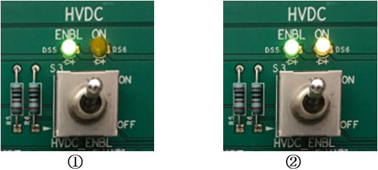
Check “HVDC On” light on the service panel (see picture). If the HVDC On LED is lit the rotor and high voltage are on.
Figure 1. LED of HVDC Switch
-
-
If the rotor is on and needs to be stopped, follow the procedure below to properly stop the rotor via the command line (Refer to Rotor Control Tool for LB Tube (VCT) in LightSpeed 7.X Service Methods for additional details):
-
Verify tube temperature is in yellow or blue TubeCare zone or temperature is <210C
-
Use command line “rotor_ctrl -stop”
-
4 System operation
Follow the recommended tube installation and calibration sequences below:
-
Perform Filament calibration, HHS Scans, and Hot ISO Alignments AFTER gantry cover installation to prevent hot landings.
-
Perform PM cleaning tasks before any calibrations or system scanning.
Follow the recommended system operation below:
-
An emergency stop shall only be used in emergency situations.
-
A console shutdown is recommended because it includes a low speed cooling delay of 30 minutes prior to stopping the rotor. There is no external indication that high voltage remains so do not remove main power until the 30 minutes’ delay is complete.
If a rotor has mistakenly been stopped while in the green TubeCare zone, take the following actions:
-
Within 90 seconds of stop event: Use “rotor_ctrl -start” command line (Refer to Rotor Control Tool for LB Tube (VCT) in LightSpeed 7.X Service Methods.
-
After 90 seconds of stop event: If rotor needs to be started, wait 15 minutes with heat exchanger running prior to starting the rotor.
Following the Tube change, the “Restart” after CSD/Replacement/New Tube Config serial number change will automatically restart the rotor.