- Topic ID: id_15460645
- Version: 2.0
- Date: Nov 8, 2018 1:36:22 AM
Table Cable Connections
-
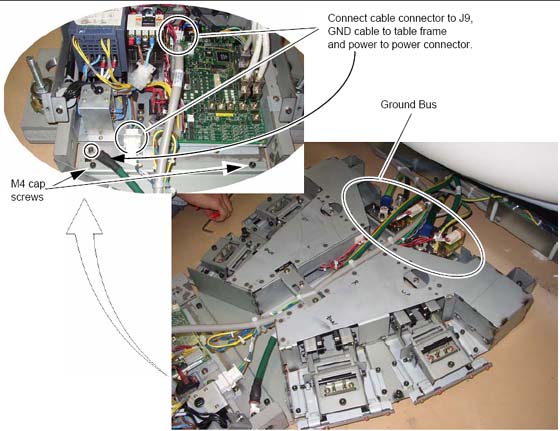
Cut the tie-wraps from around the cables in the gantry base and route the power cables from the gantry as shown in Figure 1 .
Figure 1. Footswitch Assembly Cable Wiring
-
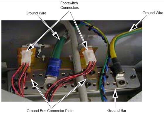
Connect the ground bus connector plate.
note:Additional M6 Hex-screws may be required to connect grounds.
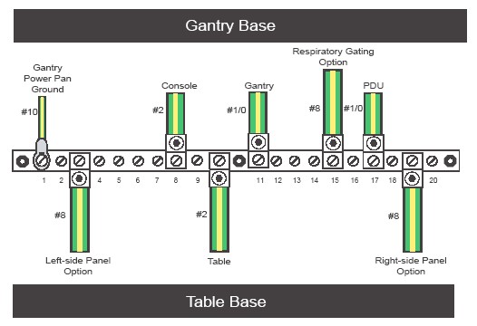
Figure 2. Footswitch Ground/Bus Bar
-
Install the footswitch pedal bracket onto the installed ground bus bar.
Connect the ground wires (not all shown in Figure 2) to the installed ground bus:
-
Table #2
-
Gantry #1/0 and #10 and 2-#8 (Optional)
-
Console #2
-
PDU #1/0
-
-
Torque per Table 1.
-
Install all footswitch covers after work is completed. See Footswitch Cover Installation.
-
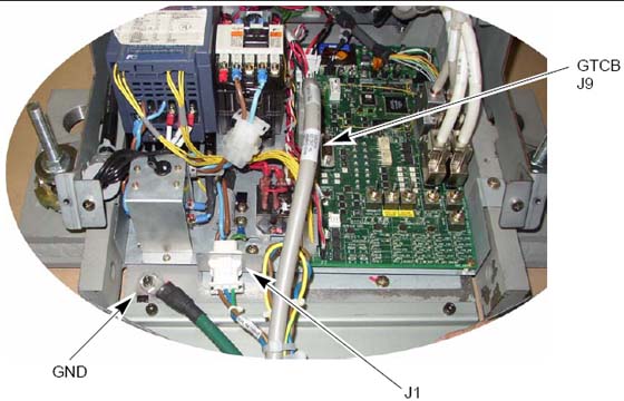
Pull and connect the cables as described in Table 2. The table cables are bundled with the gantry frame. Cut the cable ties to release bundles of cables.
note:The footswitch connector and wiring harness may be run and secured to the ground bar assembly.
Figure 3. Table Connections
 note:
note:You need to add the table ground cable and the footswitch adapter plate to ground bar, as shown.
Figure 4. Finished Ground Bar Connections
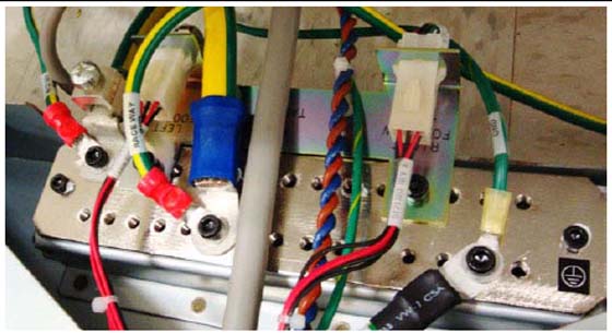
Figure 5. Table-Gantry Raceway Bus - Grounds
Various types and sizes of wire are used to ground the system. Please use the type and sizes specified in Table 3.
All connections should be torqued to the values in Table 4.