- Topic ID: id_15460647
- Version: 2.0
- Date: Nov 8, 2018 1:36:22 AM
System and Console Configuration
1 Determine System Configuration
1.1 Preparation
For convenient removal and use during installation, System Configuration Data Sheets are located in System Configuration Data Sheets.
Below is a summary of key information, some of which is required from the customer, to complete system configuration. When gathering this information, refer to Configure Site Specific Setup in Configure Site Specific Set Up.
System File Information:
-
Hospital name (Ask the customer for ALL related fields.)___________________________
-
Service ID________________________________________________________________
Patient Info:
-
Next MOD#_______________________________________________________________
-
Exam #, Diagnostic # 50000 default___________________________________________
-
Click YES to regenerate database.
-
Click NO for Mobile System.
-
HIPAA ___________________________________________________________________
Preference File Information:
-
Doctor’s title______________________________________________________________
-
Date Format______________________________________________________________
-
Time Format______________________________________________________________
-
Language type_____________________________________________________________
-
Selected Fast Cal KV’s – default - ALL unless instructed otherwise___________________
-
Dose Information – default - Unless instructed otherwise___________________________
-
Dicom – default - Unless instructed otherwise___________________________________
Hardware File Information:
-
Select table type GT 2000 or GT 1700__________________________________________
-
Default for all others
-
Network printer – default_____________________________________________________
Network file Information:
-
Suite Name – (from FE or hospital)____________________________________________
-
Host Name – (from FE or hospital)____________________________________________
-
IP Address_______________________________________________________________
-
Net Mask ________________________________________________________________
-
Broadcast Address_________________________________________________________
-
Default Gateway___________________________________________________________
-
Advanced options – default - Unless instructed otherwise by the FE____________________ ____________________________________________________________________________
1.2 System Configuration Data Sheets
1.2.1 Requirements
Record valuable system information in the data sheets that follow. Consult with your customer or network administrator to obtain the information. Understanding how the customer plans to use their CT scanner and their network and filming expectation reduces the time required to reconfigure the system.
1.2.2 Manual Film Composer Options
1.2.3 System Network Configuration
HOST ETHERNET ADDRESS
_________:_________:_________:_________:_________:_________
1.2.4 Network Application (Image Transfer) Configuration
Record the network application (image transfer) configuration.
1.2.5 Camera Application Configuration
Record the camera application configuration for the DASM or DICOM print camera.
2 Configure Site Specific Set Up
The document collector box that arrived with your system contains the Software Installation Procedures manual, which documents the reconfiguration procedure in more detail.
2.1 Preparation
On the following screens, you should make the changes necessary, pressing the corresponding button at the top of the screen to move from screen to screen. When you are done, you can either press the ACCEPT button to start the reconfiguration process, or press the QUIT button to exit without changing the system configuration.
While the reconfiguration is going on, messages are displayed in a shell window that closes when reconfiguration is complete. Should you later want to review the reconfiguration output, it is logged in:
/var/adm/install.log. YYYYMMDDWWWHHMMSS
Where
YYYYMMDDWWWHHMMSS is the Date/Time that the reconfiguration was started.
To view the file, type: more /var/adm/install.log.YYYYMMDDWWWHHMMSS
It is possible to abort the reconfiguration while entering information on the reconfiguration screens. Press the QUIT button at the top of the screen. There is NO safe way to abort the reconfiguration after pressing the ACCEPT button. If the entries made in the screens were incorrect, DO NOT try to stop the reconfiguration, instead wait for it to complete, and rerun reconfig, entering the correct parameters.
2.2 Procedure
-
Shut down applications from the Service Desktop.
-
In an xterm window, log in as root:
-
Type: su - ENTER
-
Type the root password; press ENTER
-
-
Launch the Install utility:
Type: reconfigENTER at the prompt.
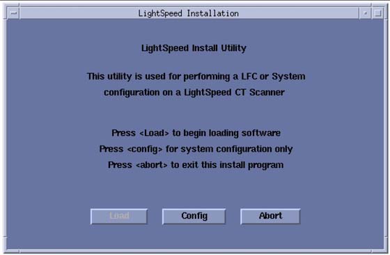
The OC displays the Install Utility Window as shown in Figure 1.
Figure 1. Install Utility Window
 note:
note:The following pages show the screens that are used to change the configuration of the system. These screens are the same as those used for the Software Configuration during Load From Cold. The actual screens vary depending on the current configuration of your system.
-
Click the CONFIG button.
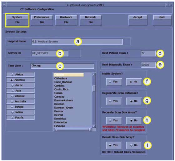
The OC displays the System Configuration - System Settings Screen as shown in Figure 2.
Figure 2. System Settings Screen
-
Configure System Settings:
-
Enter the Hospital Name.
-
Enter the Service ID.
-
Select the Time Zone for this site.
Use the scrollbar at the bottom of the time-zone selection list to view the entire description of a time-zone, to ensure that you are selecting the correct time-zone for your location.
If the time-zone of your location is not in the list, select one of the universal times in the selection menu. In this case, automatic changes for daylight savings time do not take effect. See the LFC manual for more information regarding time-zone setting and selection
-
At Next Patient Exam #, enter 1 (during installation only; this is customer-selected).
-
Next Diagnositc Exam #, enter 1 (during installation only; this is customer-selected.
-
Mobile System, select the correct answer for this installation site.
-
Regenerate database. Select YES if this is an installation with no customer data present.
note:This destroys any Scan Data present.
-
Recreate Scan Disk Array: Not used during system installation.
-
Rebuild Scan Disk Array: Not used during system installation.
-
-
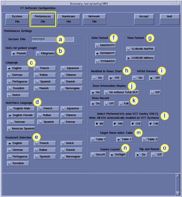
Click the PREFERENCES button to display the Preference Settings Screen as shown in Figure 3 for VCT Example.
VCT example below:Figure 3. Preferences Setup Screen (VCT Only)
-
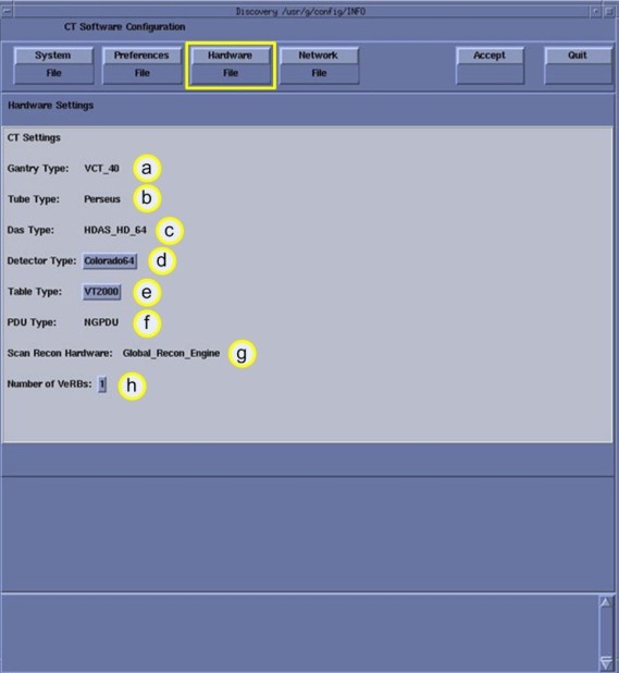
Click the HARDWARE button to display the Hardware Settings Screen for VCT see Figure 4.
Figure 4. VCT Hardware Settings VCT
-
Configure Hardware Settings
-
Review the information for Gantry Type, Tube Type and DAS Type for this system.
-
Select the Table Type installed with this system.
Determine the Table Type using the product locator card shipped with the order information.
-
Review the PDU Type and Number of VeRBs for this system.
-
-
Click the NETWORK button to display the Network Settings Screen, as shown in Figure 5.
note:This screen provides the ability to declare the CT system on a hospital network. Key information such as Host Name, IP Address, Net Mask (for CT systems on a subnet) must be obtained from the hospital network administrator.
See Install and Verify Customer Imaging Options for more information and complete details of setting the Hospital/System Network Configuration.
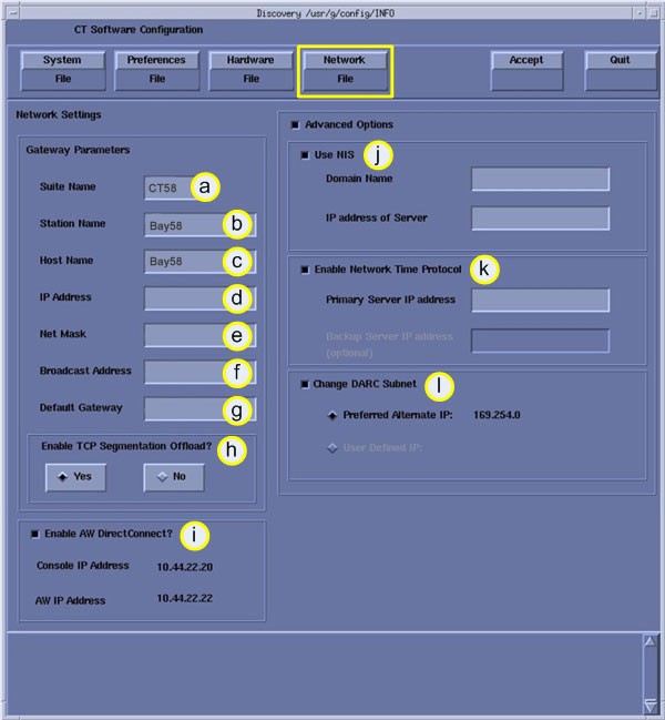
Figure 5. Network Settings Screen:
-
Configure Network Settings:
-
Enter the Suite Name.
The Suite Name must start with a letter, followed by three alphanumeric characters. Total must be four characters long. The name of the OC interface is <Suite Name>_OC, within the scanner's subnet. Typically, you should use su01 or ct01 (“su” and “ct” must be lowercase), unless the customer prefers a different suite name.
-
Enter the Station Name.
-
MUST NOT exceed 16 characters
-
MUST only contain the following characters: a though z, A through Z, and 0 through 9.
The Station Name is typically stmary or ct01
NOTE: If left blank, the Station Name defaults to the Host Name.
-
-
Enter the hospital provided Host Name. The Host Name identifies the network host name and AE Title of the CT system to the hospital's network. The Host Name:
-
MUST NOT exceed 16 characters
-
MUST only contain the following characters: a though z, A through Z, and 0 through 9.
-
Must have at least one of the following characters: a though z, A through Z. (Host Name MUST be Alpha or Alpha-Numeric)
The Host Name is typically stmary or ct01
-
-
Enter the hospital provided IP Address for the system.
-
Enter the hospital provided Net Mask for the system.
-
Enter the hospital provided Broadcast Address for the system.
-
Enter the hospital provided Default Gateway IP Address for the system.
-
Enable TCP Segmentation Offload - Default YES. If Network transfers to certain PACS systems are slow, this can be set to NO and may increase the transfer speed.
-
Enable the AW DirectConnect, if option is provided with system. Review the order information to see if option is included.
note:Items j - l are visible only when Advanced Options is selected.
-
Enter the hospital-provided NIS Domain Name and IP Address for the system, if NIS is utilized on-site.
-
Enable the Network Time Protocol, if instructed to do so by the hospital. Hospital must have an NTP Server available and the scanner should be synchronized with the Hospital's time.
-
Enable Change DARC Subnet, if instructed to do so by the hospital.
NOTE: Only enable this feature if there is an IP conflict between the system local network and the hospital local network. The GOC6 console utilizes a DHCP Server to configure the Console local network address for communications between Host, Gantry/Table and Reconstruction Engine Computers. Default local addresses in the GOC6 console use the following local Octets: 172.016.xxx.xxx
-
-
Review all screens to be sure the information is correct before proceeding to the next step.
-
Click the ACCEPT button to accept the changes made. See Figure 6
Figure 6. Accept Button
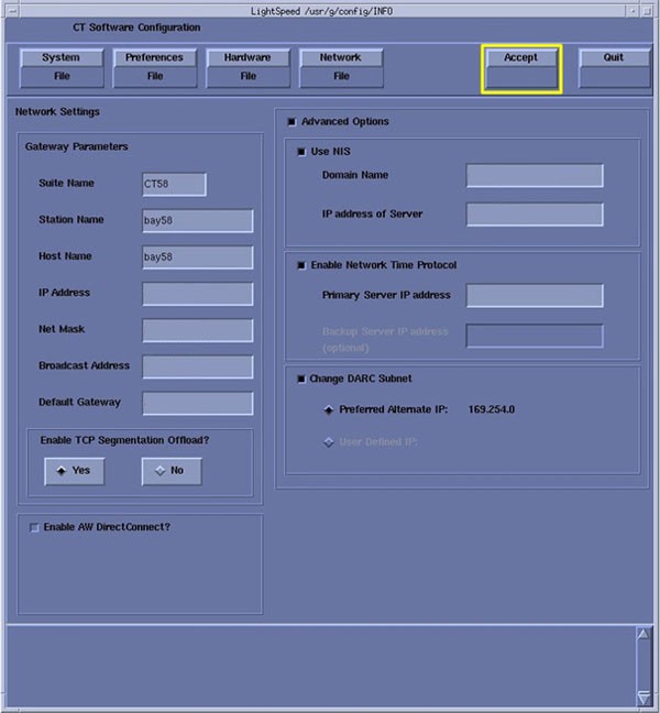
After clicking ACCEPT the system configures the system. While the configuration is going on, the results are displayed in a Shell window that closes when the loading process is complete.
-
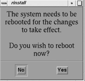
When the configuration changes are complete, the system displays a prompt to reboot. Click on YES. (See Figure 7.)
Figure 7. Reboot Screen
-
The system automatically logs in as ctuser after the reboot. Select OK on the Autostart Disabled popup message.
-
Open a Shell window.
3 Set Time and Date
 |
|
-
Open a Unix Shell and log in as root:
-
Type: su - ENTER
-
Type the root password; press ENTER
-
-
Set the date and time for your time zone by updating the fields in the setdate routine.
-
Type the following: {root@hostname}# setdate
note:Type q to quit at any time; press ENTER to proceed.
To be accurate, this tool prompts you to enter the Second. Watch your clock or PC carefully to enter the proper value, and press ENTER at the right second to set the accurate time. Press ENTER to proceed.
-
Type the current Year (1980-2030).
-
Type the current Month (1-12).
-
Type the current Day (1-30).
-
Type the current Hour (Military time, 0-23).
-
Type the current Minute (0-59).
-
Type the current Second (0-59).
\Updating the time on the OC and DARC, Please Wait…
Ping darc (172.16.0.2) 56(84) bytes of data.
-
-
Boot system to application level.