- Topic ID: id_15460112
- Version: 2.0
- Date: Nov 8, 2018 1:39:45 AM
NIO64 (Z820) Computer Theory
1 Host Computer Z820
Host Computer in GOC6.6 VCT console is the central operation controller of the CT system.
Host Computer controls all the GOC6.6 VCT console functions and data flow, including actual image generation. Software in Host computer sends the reconstruction request, recognize the recon mode, timing, parameters, and data, and be able to generate the image set. The raw data is first restored from the disks. The Host Computer then creates an image set and requests image generation to the IG process in Host Computer. While most of the software components (e.g. Recon_Control, Data_Restore, Image_Buffer, and Data_Acq) reside on Host Computer, the components related to image generation also reside on Host Computer.
Main data flow of the Host Computer is described as follows:
-
Receive raw data from the Gantry
-
Store the raw data to the scan data disks
-
Restore the raw data from the scan data disks and transfer to buffer memory in Host Computer.
-
Take multi-image streams from Image generation processes ran on Host computer, and be saved on image disk in Host Computer.
The Host Computer is comprised of the following:
-
HP computer: a computer using a high-performance PC workstation
-
System disk: the OS and Applications software are stored on this disk
-
Image disk: Images are stored on this disk
-
Scan data disks: the raw data are stored on five scan data disks (RAID5).
-
FDIP card: the DAS Interface Processor Card
-
Gigabit Ethernet (GbE) cards
-
DVD-ROM drive: will be used for software installation and stand-alone use
-
RAID card: connect to five scan data disks.
-
Graphics board: connect to two LCD monitors
-
GPU: an optional graphic card is used for 16 FPS image reconstruction, ASIR or Fluoro option.
1.1 Motherboard
The Host Computer will take advantage of a standard, off-the-shelf motherboard, using dual microprocessors to increase processing density. The Host Computer will use very high performance general-purpose processors, memory, and a server motherboard with GB Ethernet and SAS port(s), and power supply.
-
Dual Processors: Intel ® Xeon™ Quad Core processors or successor
-
Memory: 32GB DDR3-1333 ECC DIMM (8x4GB)
-
Onboard SAS Devices: four (4) SAS ports reside on mother board
-
Seven (7) PCI/PCI-X/PCI-E expansion slots.
-
SLOT 1 PCI-E: FDIP card
-
SLOT 2 PCI-E: Graphics card
-
SLOT 3 PCI-E: Not used
-
SLOT 4 PCI-E: RAID Controller
-
SLOT 5 PCI-E: Dual Part Gigabit Ethernet card
-
SLOT 6 PCI: GPU card
-
SLOT 7 PCI-E: Not used.
-
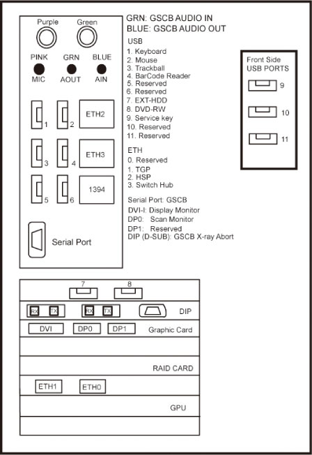
1.2 Component ID
The following picture show the Z820 panel and component ID.
Figure 1. Z820 Front Panel
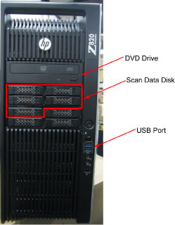
Figure 2. Z820 Rear Panel
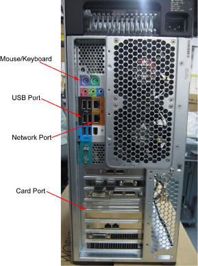
Figure 3. Mother Board
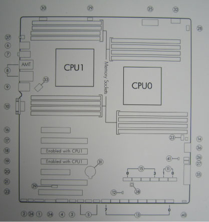
Detail
Figure 4. Z820 Left Side View
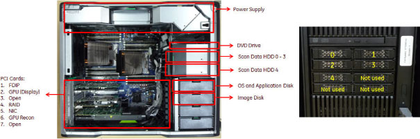
1.3 Disk Drives
There are two (2) SAS hard disk drives (300GB) and five (5) SAS hard disk drives for scan data connected to RAID card in Host computer. Below are the definition of these four hard disk drives:
-
SAS0: System disk
-
SAS1: Image disk
-
SAS3: Scan data disk 1
-
SAS4: Scan data disk 2
-
SAS5: Scan data disk 3
-
SAS6: Scan data disk 4
-
SAS7: Scan data disk 5
Below are key performance specifications of the system/image hard disk drives:
-
Minimum rotational rate of 10,000 RPM
-
SAS interface (6 Gigabits/second burst rate)
-
Formatted capacity of 300 Gigabytes
-
Form Factor: 2.5” half height form factor
Below are key performance of the scan data drives.
-
Minimum rotation rate of 10,000 RPM
-
SAS interface
-
Formated capacity of 300 Gigabytes
-
3.5” full height
Five Scan Data Disks are connected to the RAID card that enables hardware RAID5 (approximately 512 Gigabytes).
1.4 FDIP Card
This PCIe FDIP card supports almost the same functionality as the current DIP in that it converts the optical signal received from the Gantry into electrical raw data and writes that data to one of the double buffers on the card. When the received data count reaches a predetermined value it will switch over to the other buffer. The Host Computer then receives this data via the PCI bus. This card supports 64bit, 66MHz, PCI bus interface with an FPGA, and should be able to support 833MB/sec data rate optical fiber interface.
1.5 Gigabit Ethernet Card
TGPU board in gantry is connected to the Host computer via Gigabit Ethernet (GbE) card connected to one of the PCI-e slots.
Gigabit Ethernet (GbE) card:
-
Dual Gigabit Ethernet ports
-
10Base-T, 100Base-TX, 1000Base-TX IEEE802.3ab compatible
-
64bit, 66MHz (or higher) PCI-e interface
-
Low profile form factor
Gigabit Ethernet card ports definition is described below:
1.6 USB Ports
The USB ports on Host Computer are used to connect the peripheral devices. The definition of USB ports is listed as below:
1.7 DVD-ROM Drive
The DVD-ROM drive is used for software installation, system diagnostics, and to support stand-alone operation of the Host computer.
2 GPU (Graphic Process Unit)
This PCI card accelerates the back-projection process of the NIO console and is plugged into PCI-e slot in the Host Computer.
This parallel beam back-projector provides the NIO console the ability to off-load the back-projection application from general-purpose processors to fully programmable hardware. This option dramatically increases the reconstruction performance per cost ratio.
Following are the high-level CTQs for the GPU card:
-
Perform parallel beam back-projection at >16fps
-
PCI-e compatible
-
Reconstruct any image matrix size up to 524,288 32bit pixels