- Topic ID: id_15460613
- Version: 2.0
- Date: Nov 8, 2018 1:37:22 AM
JEDI - Switches, TPs, Fuses, LEDs (Pro, RT, VCT)
This module contains the following information:
-
Introduction - Introduction
-
Power On Self Tests - Power On Self Tests
-
CT IF HP V2 Board - CT IF HP V2 Board
-
PPC KV Control V2 Board - PPC KV Control V2 Board
-
DC MEAS DISCH Board - DC MEAS DISCH Board
-
GATE_HERCULE Board - GATE_HERCULE Board
-
KV_MEASURE HP Board - KV_MEASURE HP Board
-
HEATER V6B - HEATER V6B
-
ROTATION Board - ROTATION Board
-
POWER HERCULE Board - POWER HERCULE Board
-
LVPS400 Board - LVPS400 Board
1 Introduction
This section provides LED, switch, connector, and fuse information for the X-Ray Generation Subsystem.
All Test Points and LEDs are easily accessible and clearly labeled. Standard color coding of LEDs shall be used:
-
RED for hazard / fault conditions
-
GREEN for OK status conditions
-
YELLOW for other conditions
There is only one jumper used in the generator (mA tube measurement accuracy verification)
2 Power On Self Tests
The LED display status offers useful visual feedback which can help to enable error-code based troubleshooting. Whenever in doubt, a useful first step is to look at the LED status display on the PPC kV control board, then check the LEDs on the LVPS400, Rotation, and Heater boards.
2.1 PPC kV Control Board Indicators
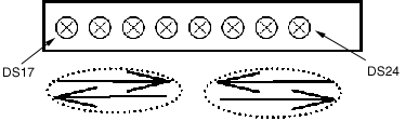
The LEDs indicating the status are the yellow LEDs, DS17 to DS24 on PPC kV control board. For the location of these LEDs, see the PPC kV Control Board block diagram in Figure 6.
2.2 LED Status
2.2.1 Power-On Diagnostics (on PPC kV Control Board)
In the figures below,  means LED ON and,
  means LED OFF.
Figure 1. DS17 through DS24
-
Power On self tests: LEDs DS17 to DS24 are lit successively several times very fast.
-
Application mode: LEDs DS17 to DS24 are lit successively more slowly. The power up self tests are completed, PPC kV control board is up and running.
Figure 2. DS17 through DS24
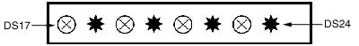
Half of the 8 LED are lit: After the download of the boot this indicates that the PPC kV control board is erasing the flash memory and preparing for the download of the application. When these tasks are done, the four LEDs on the right will be lit as shown in the following figure.
Figure 3. DS17 through DS24
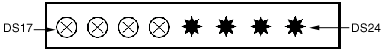
Half of the 8 LED are lit: Normal after the download of the boot. This can also indicate a corrupt software problem or database checksum problem. In case of software problem communication with the generator will not be possible. Try to download again the software or replace PPC kV CTRL board. In case of database problem, an error code is logged and communication with the generator is possible. Refer to error code description.
Figure 4. DS17 through DS24
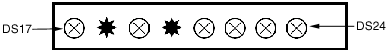
When an application error occurs, LEDs blink indicating the simplified error code in binary code. When the error is cleared, the 8 LEDs are lit successively.
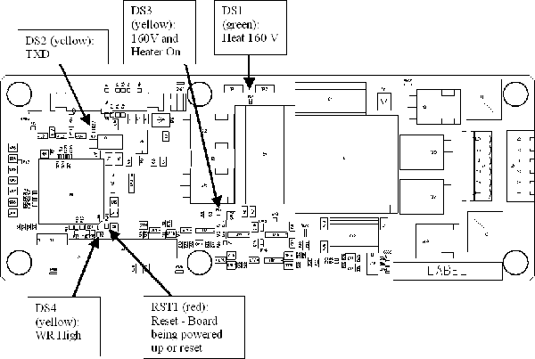
2.2.2 Heater Board
After the power on diagnostics, heater board LEDs DS1 and DS2 are lit successively. Refer to block diagrams for complete explanation of LED indication on this board. Any different status corresponds to an abnormal situation. An error code is logged. Refer to error code description.
2.2.3 Rotation Board
See block diagrams.
After the power on diagnostics, rotation board LED DS5 is blinking. Refer to block diagrams for complete explanation of LED indication on this board. Any different status corresponds to an abnormal situation. An error code is logged. Refer to error code description.
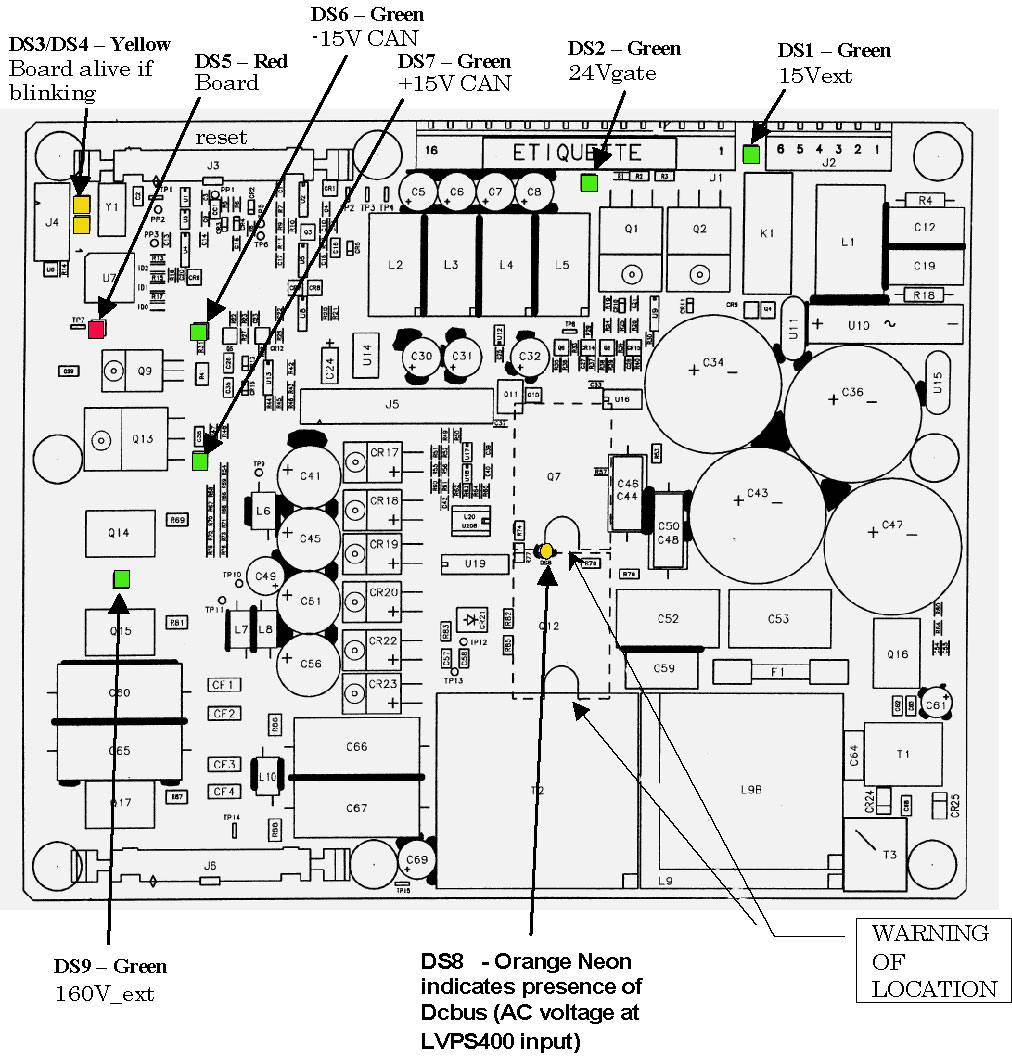
2.2.4 LVPS400 Board
See block diagrams
After the power on diagnostics, LVPS400 board LEDs DS3 and DS4 are lit successively. Any different status corresponds to an abnormal situation. An error code is logged. Refer to error code description.
3 CT IF HP V2 Board
3.1 Board Location
JH4 Inverter
Figure 5. CT IF Board
3.2 Board Connections
3.3 Board Test Points
4 PPC KV Control V2 Board
4.1 Board Location
JH4 Inverter
 |
|

Figure 6. PPC kV Control Board
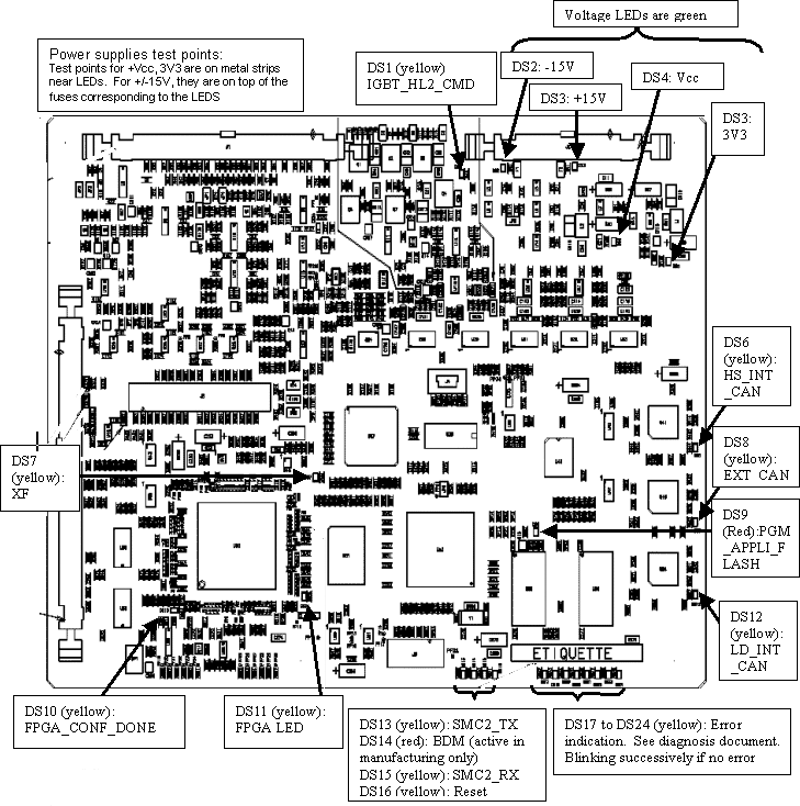
Power supplies test points:
-
Test points for +Vcc, 3V3 are on metal strips near LEDs.
-
For +/-15V, they are on top of the fuses corresponding to the LEDS
4.2 Board Connections
4.3 Board Switches and Jumpers
4.4 Board Indicators
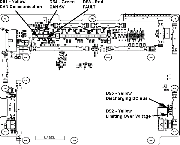
5 DC MEAS DISCH Board
5.1 Board Location
JH4 Inverter
|
Figure 7. DC MEAS DISCH Board
For a larger PDF version of the above image, click on the following PDF icon, 308188.pdf.
5.2 Board Connections
6 GATE_HERCULE Board
6.1 Board Location
JH4 Inverter
Figure 8. GATE_HERCULE Board
6.2 Board Connections
7 KV_MEASURE HP Board
7.1 Board Location
JH4 MPHVT
 |
|
Figure 9. KV_MEASURE Two Tubes Board
7.2 Board Connections
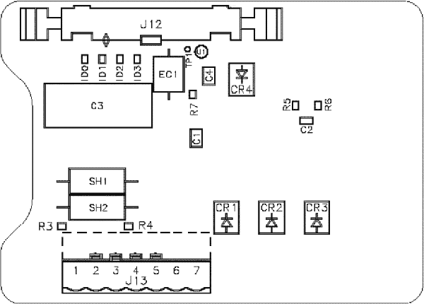
8 HEATER V6B
8.1 Board Location
JH4 Auxiliaries
|
Figure 10. HEATER V6B Board
For a larger PDF version of the above illustration, click on the following PDF icon, 308206.pdf.
8.2 Board Connections
9 ROTATION Board
9.1 Board Location
JH4 Auxiliaries
|
Figure 11. Rotation Board
For a larger version of the above illustration, click on the pdf icon below:
Figure 12. Rotation Board
252359.pdf9.2 Board Connections
9.3 Board Test Points
9.4 Board Indicators
I
10 POWER HERCULE Board
10.1 Board Location
JH4 Inverter
Figure 13. POWER HERCULE Board
10.2 Board Connections
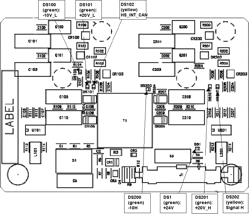
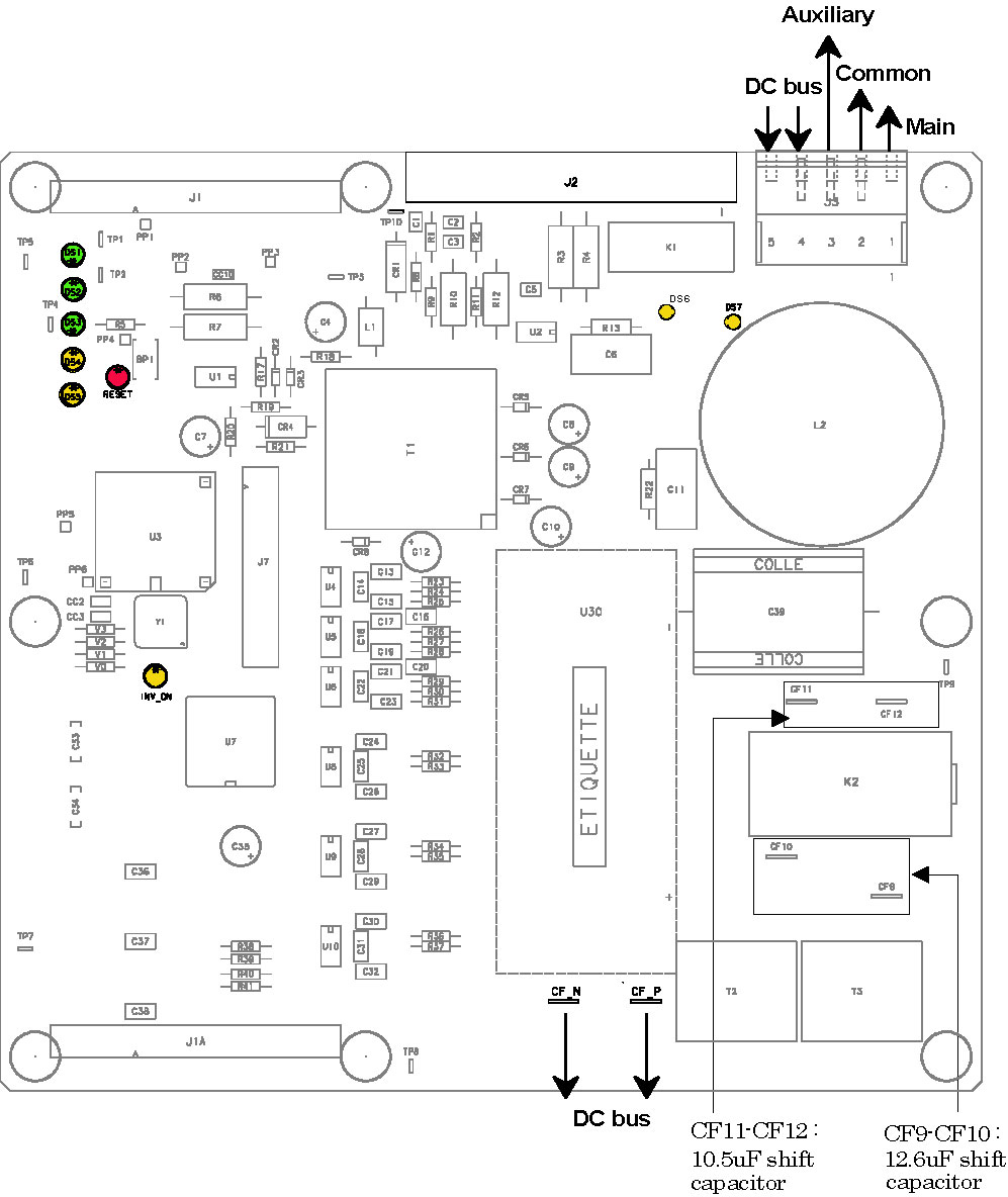
11 LVPS400 Board
|
|
Figure 14. LVPS400 Board
For a larger version of the above illustration, click on the pdf icon below:
Figure 15. LVPS400 Board
252394.pdf