- Topic ID: id_15460199
- Version: 3.0
- Date: Sep 30, 2019 9:31:20 PM
Interposer Replacement Procedure
1 Personnel Requirements
2 Procedure Overview
This procedure describes and illustrates the steps needed to replace interposers on a Halo, Halo-Saturn, HD750, or Sherlock detector.
3 Preliminary Requirements
3.1 Tools and Test Equipment
-
ESD Mat and Wrist Strap
-
Standard FE tool kit
-
FE Torque Wrench Kit (46-268445G1 or 5135228 or equivalent).
-
Torque driver capable of torqueing from 3 to 22 lb-in.
As an option, if you had four torque drivers, one set to 3 lb-in and another set to 7 lb-in the process to replace interposers would be more efficient. To install the module one torque drive set at 10lb-in and another set to 3.5 lb-in for the Digital Cable Screw.
-
Tie-wraps as required
-
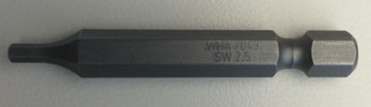
HEX BIT 2.5MM with 0.25 inch HEX Shank, 1.9 inch length (shown below).
-
HEX BIT 3.0MM with 0.25 inch HEX Shank, 1.9 inch length (shown below).

Optional Tools:
-
Module alignment gage (order from Tool Depot when working with modules 27-31) – 5172309 Not required reference only
-
Deionizing fan – 2335059 OPTIONAL
3.2 Replacement Parts
3.3 Safety
|

|
 |
|
3.4 Required Conditions
4 Procedure
Overview:
The procedure will include the following steps:
-
Identify module location.
-
Preparing for replacement.
This step will direct you to prepare a clean, well-organized work area to replace the interposers. ESD mat, wrist strap, and Nitrile gloves are required.
-
Opening up the detector to access the modules.
You will be directed to the Service documentation for plenum and FRDM removal instructions.
-
Pulling modules and replacing interposers.
You will pull ONE module at a time, to insure proper module alignment and reduce the risk for damage to the detector collimator. Be CAREFUL when pulling out and inserting the module to prevent damage to the digital cable if it rubs against the neighboring module. It is CRITICAL to ensure the modules get returned to the same location.
-
Retesting FRDM alignment Wizard, reference the Service documentation.
-
Replacing covers, reference the Service documentation.
-
Calibration and Finalization, reference the Service documentation.
-
Ensure that you have the tools needed to remove modules.
If you do not have the tools to remove the module, contact your regional support leader for the Detector Digital Module Field Replacement Accessory Collector.
4.1 Module Location Identification
A few detectors manufactured between 2013 and 2014 may have substandard interposers. The typical interposer failure mode is an open Channel see following example below.
Replacing interposers will not solve all open channel errors.
4.2 Preparation for Replacement
The following section will prepare the system and a work space for clean interposer replacement.
|
|
|
|
-
Prior to beginning the interposer replacement it is important to check current FRDM alignment to establish a baseline for comparison later. Follow the below steps to review the systems current alignment:
note:If any modules are out of alignment, it is recommended to wait until interposers have been replace to attempt alignment.
-
From the Common Service Desktop, Utilities Menu, Open a Shell and type: zalignmentWizardEnter .
note:zalignmentWizard will NOT open from a regular unix shell, it must be opened from the Utilities Menu in CSD.
-
The alignment check will run 2 stationary scans and show plots as shown in Figure 1. Processing will take approximately 2 minutes after the scans are run.
-
Save as a copy of the output as a jpg in the usr/g/scripts directory.
Figure 1. Alignment check Display
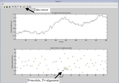 note:
note:Refer to FRDM Replacement Procedure, Section 3.7 step 3 for additional information regarding current alignment.
-
-
Clean and Organized Workspace Preparation.
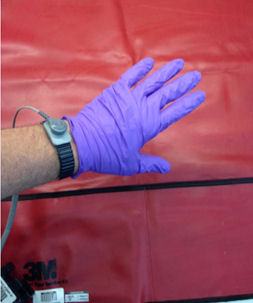
Figure 2. ESD wrist strap and Nitrile gloves
- notice
-
Locate a clean surface and place an ESD mat to use as a work area. The detector module is very sensitive to ESD and dust; it needs to be handled with care.
-
Clean all work surfaces, including the ESD mat, the work area must start off clean and organized. A comfortable chair and table should be used to ensure a quality interposer replacement.
-
Ensure gloves and ESD strap are on and properly connected.
-
Gather the following at the workspace.
-
T10 torx bit.
-
M3 button head screws from kit(s).
-
One Torque driver capable of 3 to 7 lb-in range (.34 to .8 N-m)
-
Static Dissipative Sheet from kit(s).
-
Alcohol Wipes from kit(s).
-
Interposers from kit(s).
-
4.3 Interposer Replacement.
|
|
Please follow Equipment Service – Lockout-Tagout-PPE procedures in Safety section of the Service Methods CD-ROM.
In the following section, the FRDM replacement procedure in the Service Documents will be referenced to provide detailed instructions for removing and replacing FRDM’s.
-
FRDM Removal: Refer to FRDM Replacement Procedure for steps to remove the modules needing interposer replacement.
note:ESD strap and Nitrile gloves are needed for FRDM removal.
-
Follow Section 3.1 Special Tools Overview
-
Follow Section 3.2 Preparing the System
-
Follow Section 3.3 Air Plenum Removal
-
Follow Section 3.4 FRDM Removal
-
-
Interposer Replacement
-
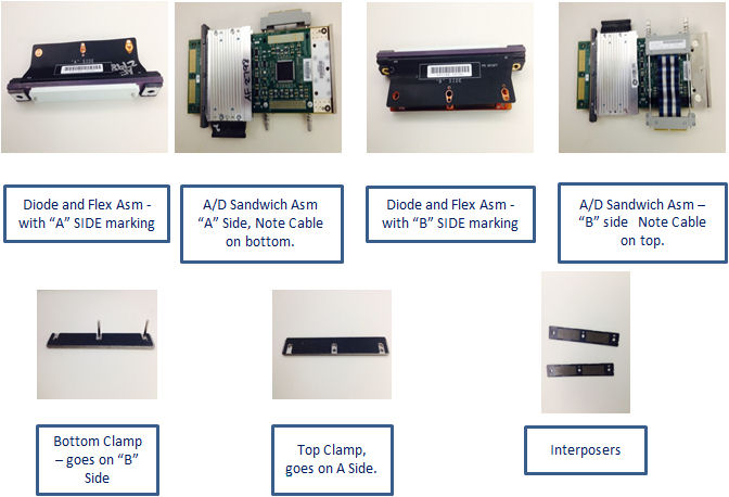
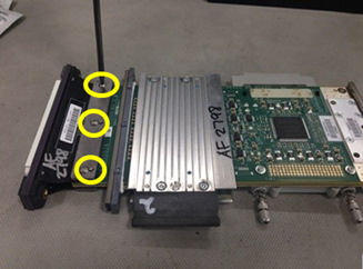
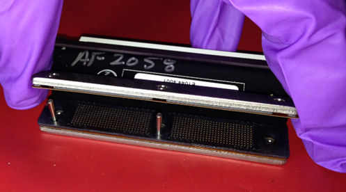
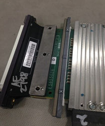
Move the FRDM module to the clean workspace prepared earlier. Place the FRDM module with the “A” side up. See Figure 3, showing the orientation of a Module with the “A” side up.
-
Using a T10 torx bit, loosen and remove three (3) M3 button head screws. Discard the screws as new ones will be used.
Figure 3. M3 Button Head Screws
-
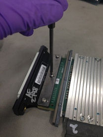
Slowly lift up the top clamp and flex (they may stick together), remove the interposer and discard. Be careful not to bend the flex too far, or damage it during removal. There is only one interposer on the ‘A’ side of outer Saturn modules.
Figure 4. Top Clamp and Flex
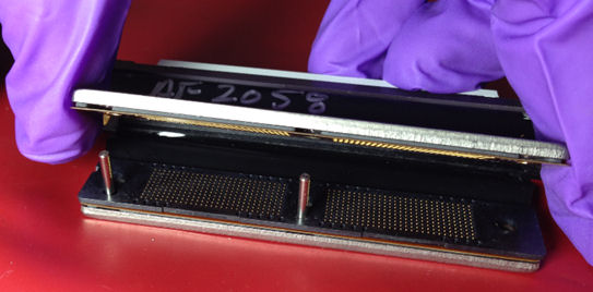
Figure 5. Top Interposer Removed
-
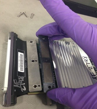
While holding the diode and flex assembly, lift up on the A/D sandwich assembly straight up and remove.
Figure 6. A/D Sandwich Assembly Removal
-
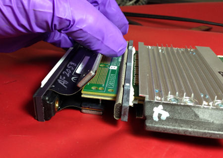
Remove the interposer from the bottom clamp and discard, see Figure 7.
Figure 7. Bottom Interposer
-
While cleaning the electronics in the following steps, there may be debris from broken interposer contacts. Ensure to collect and remove any debris found.
note:The gold particles are extremely conductive and could cause significant damage to the electronics.
-
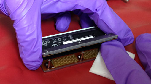
Carefully clean the contact pads of the A/D sandwich on both sides using the provided alcohol wipe. Always use a new alcohol wipe for each module.
Figure 8. A/D Sandwich contact pads cleaning
-
Carefully clean both contact pads on the flex with the provided alcohol wipe. Be careful NOT to touch your fingers directly to the contact pads on the flex. Be careful to not bend the flex too much, it can get damaged.
Figure 9. Flex pads cleaning
-
Wait one (1) minute for the alcohol to dry before proceeding. Discard the alcohol wipe.
note:It is important that the alcohol dries completely before proceeding. If the alcohol is not dry, it can cause leakage and noise failures.
-
Before proceeding to assemble the new interposers, carefully examine the flex contacts under a light source to ensure that no small particle or residue remain.
-
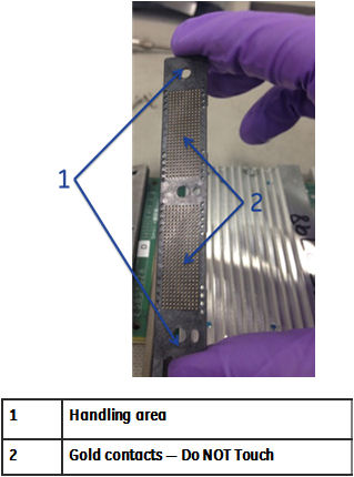
Carefully remove one interposer from the package. Only handle the interposer by the ends and absolutely AVOID touching the gold contacts on the interposer.
note:For outer modules on Saturn detectors the module will only contain one interposer.
Figure 10. Interposer Package
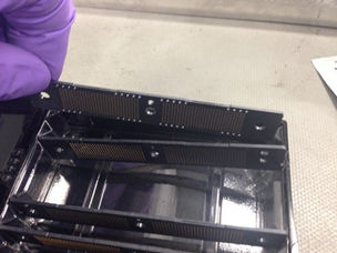
Figure 11. Interposer Handling
-
Place the interposer on top of the bottom flex, the alignment pins on the bottom clamp will guide the interposer into the correct position. Be careful NOT to touch your fingers directly to the contact pads on the flex.
note:The guide pins go into the small holes and the screws into the large holes.
Figure 12. Bottom Interposer Install

-
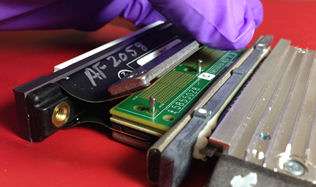
Position the A/D sandwich with the ribbon cable side down and place it on top of the bottom clamp and interposer.
Figure 13. AD Sandwich Aligned to Bottom Clamp
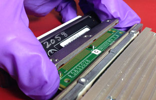
Figure 14. A/D Sandwich Installed
-
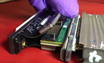
Carefully take another interposer from the package and place it top of the A/D sandwich assembly.
Figure 15. Top Interposer Install
-
Place the flex and top clamp over the top interposer.
Figure 16. Top Clamp Reinstalled
-
Install three (3) new M3 button head screws from the procedure kit onto the clamp, finger tighten only. Ensure the top and bottom clamps are evenly engaged.
note:Ensure you use new screws provided in the kit. Using existing screws may cross thread or gall and prevent proper clamping of the joint.
Figure 17. M3 Button Head Screws
-
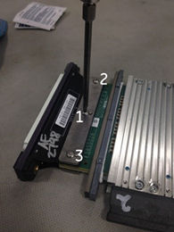
Torque the three (3) M3 button head screws starting at the center (1), then top (2), and then bottom (3). See Figure 18 and Table 1.
Figure 18. Torque Pattern
 note:
note:The torque spec for these M3 screws are specific to this instance and may differ from the re-torque procedure in the FRDM replacement procedure in the Service Documentation.
-
Reinstall the detector module, refer to the FDRM Replacement Procedure, Section 3.5 of the (Discovery CT Series Service Methods — Replacement — Gantry — DAS and Detector). Check the ribbon cable on the FRDM so that it is not sticking out too far prior to installing back into the detector.
-
-
Module Alignment Check (gantry covers off). When all interposers are replaced, check the alignment of the modules. This can be done once before the detector will over heat without the plenum installed. Check alignment by doing the following:
note:Only look at the Modules you replaced interposers. Do NOT move other modules. Some Factory installed modules may not be within this specification.
-
Ensure that the rotational lock is engaged.
-
Ensure that the front display is connected to satisfy e-stop.
-
Apply the HVDC and the 120VAC power ONLY. Do NOT turn on the axial drive switch.
-
In Common Service Desktop under the Utilities menu, open a Shell window and type: zalignmentWizardEnter .
note:The following window will pop up to indicate X-Ray will be created. Ensure that the gantry is locked and Axial Switch is off, the click Confirm.
note:Be sure to no leave the systems powered up for long without the plenum, this can cause the detector to overheat.

-
The alignment check will run 2 stationary scans and show plots as shown in Illustration 22. Processing will take approximately 2 minutes after the scans are completed.
-
Refer to FRDM Replacement Procedure, Section 3.7 step 3 for information regarding current alignment.
-
Make alignment adjustments as needed, typically, the alignment wizard can only be run once without the Plenum and Light Seal Installed. Without the plenum installed, airflow will be altered and the detector may overheat and shut down.
note:At this point, the saved baseline scan from earlier can be reviewed as a reference but it is not necessary. The before and after do not have to match, the ‘after’ needs to be in specification.
-
-
Detector Testing: When alignment testing without Plenum and Light Seal is complete, continue with the FRDM Replacement Procedure and Detector testing.
-
Replace Light Seal Cover and cover bands per Steps 3.5.13 and 3.5.14 of FRDM Replacement Procedure.
-
Re-install Plenum per step 3.6 of FRDM Replacement Procedure.
-
Complete Detector Testing as outlined in Section 3.7 of FRDM Replacement Procedure.
-
-
Install all gantry covers remembering to enable Axial Drive just before installing gantry right side cover.
Refer to Replacement → Gantry → Enclosure → (Cover Removal Procedures).
note:Gantry covers MUST be in place and detector up to proper temperature prior to running full calibrations.
-
System Calibration: Complete the FRDM Replacement Procedure (Section 9 System Calibration).
4.4 Finalization
-
Test scans done as part of FRDM Replacement Procedure.
-
Perform a [Save State] to save the new calibration data.
-
Remove all of the old parts from the site and dispose of it.
5 Appendix A
Factory Torque Spec for Detector module Clamp Screws (Flex Connection Screws)
This is different than the specs in the Service Procedure.
-
Detector Module Screw:
-
Digital Cable Screw:
-
Light Seal Screw:
-
Screw Cover Band:
-
Plenum top and side M8 screws:
-
Plenum bottom M6 screws:
-
Fan Plate Screws:
-
Cable Safety Covers over the CFC and DHC, for 2006 style Plenum: