- Topic ID: id_15460661
- Version: 2.0
- Date: Nov 8, 2018 1:36:02 AM
Equipment Service - NGPDU
For a full size version of this illustration, click on the pdf icon below
Figure 1. Full Size Illustration: NGPDU Front & Rear (exposed view)
81432.pdfFigure 2. NGPDU Front & Rear (exposed view)
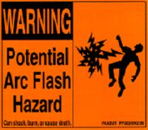
The PDU must be de-energized prior to performing work on it. More than 100 Kilowatts of power exists in the PDU at various periods of time. Therefore, consider all points in the PDU as hazardous.
Figure 3. Arc Flash Hazard
 |
|


1 Electrical
1.1 Potential Hazards
-
Axial drive power for gantry rotation (AC)
-
High voltage DC for X-ray generation (floating DC)
-
Distributed console, table and gantry power (AC)
1.2 Hazard Awareness Indicators
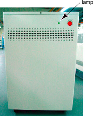
A small power lamp is visible on the front cover. When illuminated, this lamp indicates power is present within the PDU. See Figure 4.
Figure 4. PDU Power Lamp
1.3 Protected Service Outlets
The service outlet is protected by a circuit breaker. The outlet is located on the Terminal panel. See Figure 2.
1.4 Circuit Breakers and Switches
CIRCUIT BREAKERS
There are three (3) groups of circuit breakers in the PDU used to protect various parts of the system. See Figure 5.
CB2 - Circuit Protection (Axial Drive).
CB3 - Full Winding Protection.
CB4 - CT Gantry Service Outlets.
CB5 - CT Gantry rotating loads.
CB6 - Table & CT Gantry Stationary Loads
CB7 - Operator Console
CB8 - PET Gantry
CB9 - NGPDU Control Power Supply
Figure 5. PDU Circuit Breakers
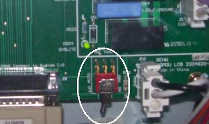
Figure 6. Switch 2 Manual HVDC (SW2-MNL HVDC)
 |
|
2 Mechanical
The PDU’s top cover is not hinged. To access the top of the PDU, loosen the top cover front retaining screw, then lift and remove the PDU top cover.