- Topic ID: id_15460095
- Version: 2.0
- Date: Nov 8, 2018 1:35:51 AM
Equipment Service - GOC6.6 Console
1 Overview & Personnel Requirements
Figure 1. Console (GOC6.6)
 |
|
2 Console – GOC6.6 Chassis Service Access Preparation
-
Apply LOTO to System. For procedures, see Equipment Service - Lockout-Tagout-PPE.
-
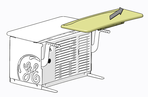
To allow for the best access to the computer and components in the Console, the GOC6.6 Chassis Keyboard Table should be removed from the chassis and set aside. This allows better access to the front of the chassis without interference.
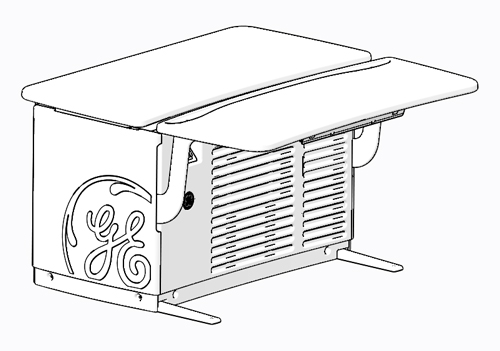
Figure 2. Console – GOC6.6 Chassis Keyboard Table
 note:
note:Before performing this task, ensure there is a place for the GOC6.6 Chassis Keyboard Table to reside without blocking emergency egress path, and there is adequate room to service product(s).
-
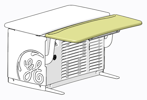
By pulling on the two (2) release handles under the GOC6.6 Chassis Keyboard Table, the keyboard table can easily be removed from the support brackets without the use of tools. After releasing the GOC6.6 Chassis Keyboard Table, lift the keyboard table away from its support brackets and set it aside being careful not to chip the laminate surface.
Figure 3. GOC6.6 Chassis Keyboard Table Release
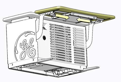
Figure 4. GOC6.6 Chassis Keyboard Table Removal
-
Remove the Console front cover. Refer to instructions from the procedure list. Unobstructed access should now be available to the GOC6.6 chassis components.
3 Console Computer
|

-
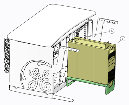
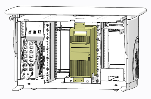
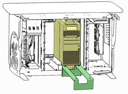
Only the Console Computer, classified as Field Replaceable Unit (FRU), needs special attention due to its associated weight. The following illustration shows this computer’s location in the center of the GOC6.6 chassis.
Figure 5. Console Computer Location
 note:
note:Though this guideline is meant to address safe access and lifting condition of the aforementioned component, this guideline also illustrates the best method for accessing all the components inside the Console computer and GOC6.6 chassis. All of the Console components are removed from the front of the GOC6.6 chassis. Access to the rear of the GOC6.6 chassis is only necessary to disconnect cabling from these components.
-
Reference the procedure of this manual for details concerning mounting hardware and cable interconnects.
4 Console Computer Service Access and Lift Assist Recommendations
4.1 Console Computer Service Access and Service Platform
-
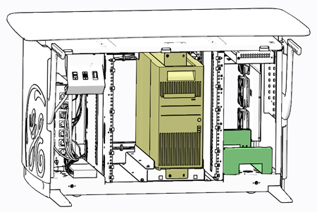
Supplied with the Console is a special Service Platform that is to used whenever accessing the Console computer or when removing or installing a replacement computer. The use of this Service Platform eliminates improper body positioning when accessing or lifting the Console computer.
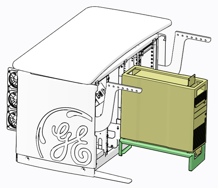
Figure 6. Service Platform Storage Location – Right Side Compartment of GOC6.6 Chassis
-
Remove Service Platform and place it in front of the Console computer. Note: The service platform has tabs which engage with console frame to keep the platform in place. Make sure the tabs have fully engaged with console frame.
Figure 7. Service Platform Removal
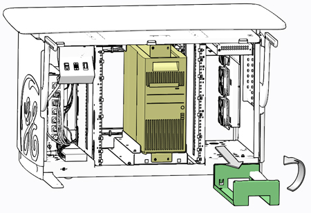
Figure 8. Service Platform Placement
-
Remove necessary hardware from Console computer’s mounting brackets and slide the computer onto the service platform, using the handle built into the top surface of the computer’s chassis.
Figure 9. Console Computer Removal from GOC6.6 Chassis – No Lifting Required
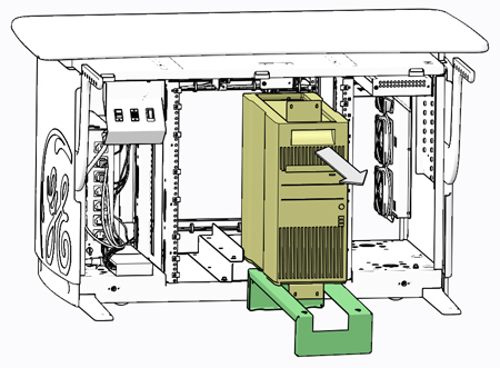
Figure 10. Console Computer Placement on Service Platform
-
Access to the Console computer is now possible without interference from the GOC6.6 chassis. Follow prescribed component replacement procedures located in the chapter of this manual for details concerning FRU replacement inside the Console computer.
4.2 Console Computer Lift Assist
-
In the event you believe you are not capable or allowed to lift the heavy computer, request that a second person assist in the computer removal and installation.
-
Otherwise, lift the Console computer by the two handles built into the top surface of the computer’s chassis.
Figure 11. Console Computer Lift Points (A & B)