- Topic ID: id_15460542
- Version: 3.0
- Date: Jun 15, 2020 10:58:08 PM
DIG Theory
1 Data Acquisition & Image Generation (DIG) Computer Overview
Figure 1. DIG Computer
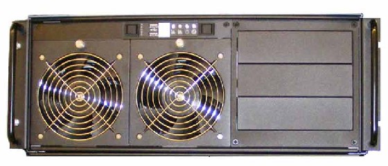
The Data Acquisition and Image Generation Computer (DIG) used in the Global Operator Console Series 6 (GOS 6) is a custom designed computer based on the Intel x86 multi-core processor server platform and manufactured by a third party vendor for GE Healthcare. The DIG Computer will have two configurations based on system utilization. The primary difference in the two DIG Computer configurations is based on the type of DAS Interface Processor (DIP) board installed inside the DIG Computer.
The DIG computers serve two purposes: raw scan data save and image reconstruction. The raw scan data is transmitted from the Data Acquisition Subsystem (DAS), across the Slip Ring, to the DIG computer. The DIG Computer saves this data to a High Speed Disk Array (HSDA) and later retrieves it for image reconstruction.
Image reconstruction is performed on DIG Computer native processors and an add-in GPU card. The Data Acquisition and Reconstruction Computer (DARC) and Image Generation Computers (IGs) previously performed these functions in earlier versions of GOC console configurations. The DIG Computer communicates with the Host Computer through the Console Network Switch (CNS) and performs a remote boot through this connection.
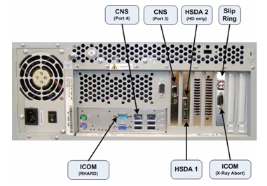
Figure 2. DIG Computer with HDIP Card (HD only)
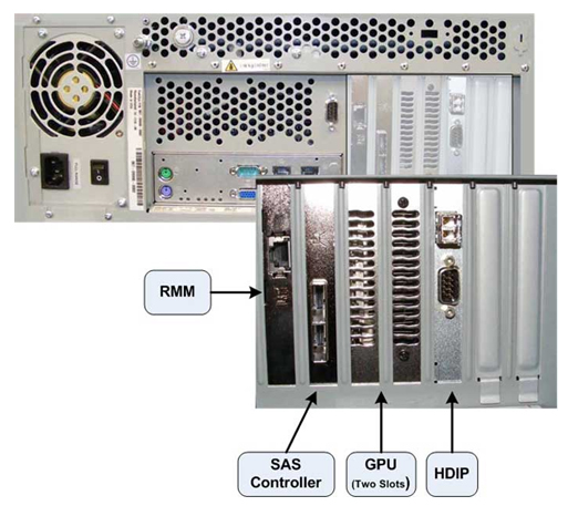
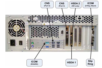
Figure 3. DIG Computer with VDIP Card (VCT)
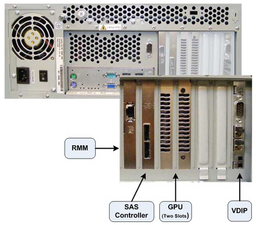
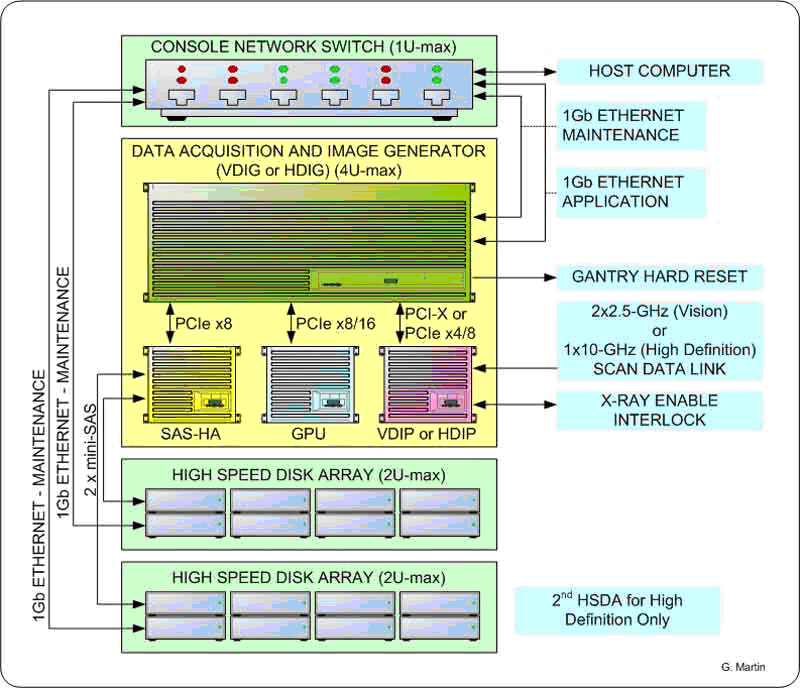
Figure 4. DIG Interconnect Diagram
The following is a brief theory overview of the hardware and software associated with the DIG Computers.
2 DIG Computer Hardware
The DIG Computer is a two (2) Quad-Core Intel® Xeon® processor (Harpertown) based computer configured by GE Healthcare utilizing the Intel Starlake (S5000XSL) server class board.
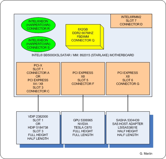
Figure 5. DIG Computer Block Diagram
2.1 Systemboard
The systemboard contained in the DIG Computer utilizes the following integrated hardware.
Dual LGA Socket J (771-pin LGA) Multi-core Intel® Xeon® Processor Systemboard with:
-
2 Intel® Quad-core Zeon® (Harpertown) 2.33 GHz Processors w/4MB shared L2 Cache
-
Front Speed Buss of 1333 MHz
-
8 Memory Slots (32 GB max.)
-
Integrated
-
Video
-
2 x GBit NIC Ports
-
USB 2.0 Ports
-
SATA Hard Disk Controller
-
-
Remote Management Module (RMM)
Complete details of the Intel® Starlake (S5000XSL) server class systemboard can be obtained from Intel® support web site http://support.intel.com.
See Figure 6 and Figure 7 for Systemboard Layout.
Figure 6. Intel® Starlake Systemboard Layout
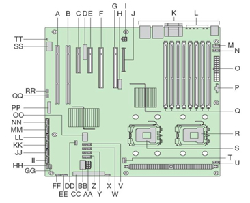
Figure 7. Intel® Starlake ATX I/O Layout
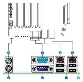
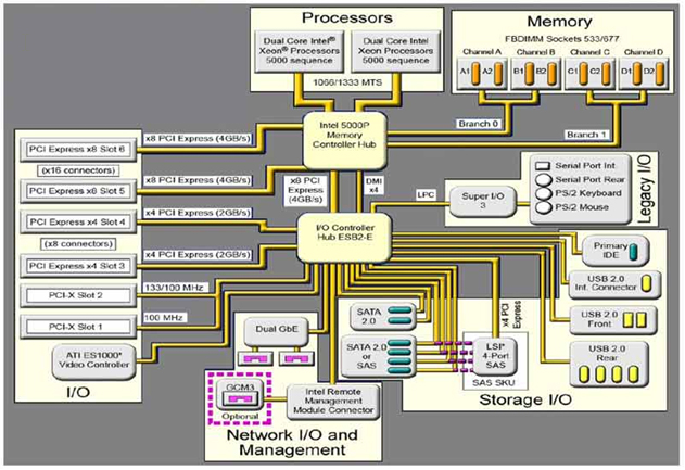
Figure 8. Intel® Starlake Systemboard Block Diagram
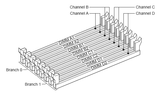
2.1.1 Memory Modules
The DIG Computer is equipped to handle up to eight (8) fully buffered DIMM Memory Modules.
The base memory configuration contains eight (8) two (2) GB, DDR2 ECC 667MHz PC5300 DIMM Memory Modules (total of 16 GB).
See Figure 9 for Memory Slot Assignment.
Figure 9. DIG Memory Slot Assignment
2.1.2 Integrated Network Interface Controller (NIC)
Network interface support for the DIG computer is handled by an integrated Dual Gbit Ethernet controller on the DIG systemboard. Each network interface controller (NIC) drives two LEDs located on each network interface connector. The Link/Activity LED at the left of the connector indicates connection when on, and transmit / receive activity when blinking. The Speed LED at the right of the connector indicates data rate. See Table 3 for NIC LED status.
Figure 10. NIC Status LEDs

2.2 SAS Controller Card - LSI™ Logic - LSISAS3801E
The DIG Computer utilizes a Serial Attached SCSI (SAS) control card to interface the High Speed Disk Array/s and is installed in Slot 6 on the systemboard. This controller is responsible for directing raw acquisition scan data coming from the Data Acquisition Subsystem (DAS) to the HSDA and later retrieves the data for image reconstruction. The LSI™ Logic - LSISAS3801E card is a 3Gb miniSAS 8 -port host bus adapter. This host bus adapter supports large capacity external storage RAID and non-RAID enclosures by connecting a PCI Express bus with two external x4 SFF8088 miniSAS connectors.
2.3 GPU Card - NVIDIA® Tesla™ C870
The NVIDIA Tesla Graphics Processor card is the main image reconstruction processor in the GRE subsystem and supplies the same functionality as the RAC boards in previous generation of the GOC consoles. The Tesla C870 card utilizes the C870 GPU which is specifically designed to handle highly parallel computation, needed for image generation and reconstruction.
Tesla C870 GPU specifications:
-
One GPU (128 thread processors)
-
1.5 GB dedicated memory
-
Fits in one full-length, dual slot with one open PCI Express x16 slot
2.4 DAS Interface Processor Card (DIP)
2.4.1 High Definition DAS Interface Processor Board (HDIP)
The HDIP card converts the optical signal received from the Gantry / DAS Sub-systems into electrical raw data and writes that data to one of the double buffers on the card. When the received data count reaches a predetermined value it will switch over to the other buffer. The DIG Computer then receives this data via the PCI bus.
• DAS Transfer Rate: 10 GBaud, single channel
2.4.2 VCT DAS Interface Processor Board (VDIP)
The VDIP card converts the optical signal received from the Gantry / DAS Sub-systems into electrical raw data and writes that data to one of the double buffers on the card. When the received data count reaches a predetermined value it will switch over to the other buffer. The DIG Computer then receives this data via the PCI bus.
-
DAS Transfer Rate: 2.50 GBaud per channel.
-
For 32-slice configuration, use channel 1 for data transfer. Do not use channel 2.
-
For 64-slice configuration, use channel 1 for transferring data from DAS A-side, and channel 2 for transferring data from DAS B-side.
-
Optical fiber channel 1 and channel 2 cannot be swapped. When channel 1 or channel 2 has the wrong data for the channel, the VDIP will generate a PCI interrupt and show “incorrect channel connection” at the interrupt status register.
2.5 Power Supply (PSU)
The DIG Computer is powered by a 400 Watts PSU. Rated voltage range 95–132 VAC and line frequency 50–60 (+/- 3) Hz, auto switching and power factor correction.
3 DIG COMPUTER CONNECTIONS
4 DIG Computer Software
4.1 DIG Computer Operating System (OS) and Application (APPS) System Software
The DIG OS and Application software is located on a dedicated Network File System on the Host Computer hard drive. Upon successful POST of the DIG Computer hardware, the DIG remote boots from this dedicated Network File System and loads the operation and application software to the DIG memory. The DIG Computer runs on a specifically configured GE Healthcare Linux OS and Application software, found on the Host Computer Operating Disk (/usr/g/darc).