- Topic ID: id_15460823
- Version: 2.0
- Date: Nov 8, 2018 1:36:21 AM
Console Cable Connections - GOC6 Series
Includes both GOC6 and GOC6.5
1 Monitor and User Tower Placement
-
Locate and unpack the two monitors from the lean cart (see Figure 1).
-
Carefully place the monitors on the console desktop.
-
Locate and unpack the media drive tower.
-
Place the media tower on the console desktop.
Figure 1. Lean Cart Layout
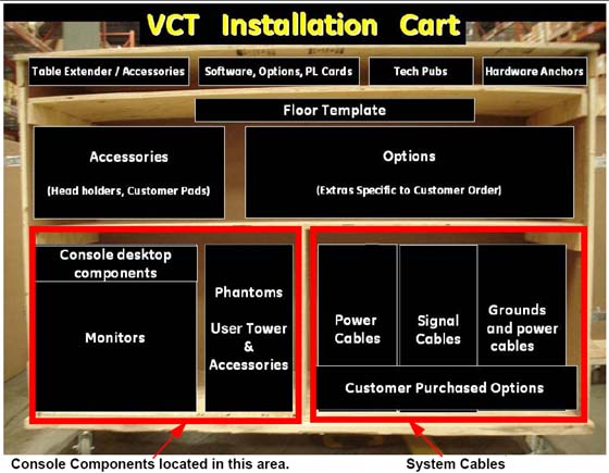
Figure 2. Global Console tabletop component placement (actual components may vary in color and configuration)
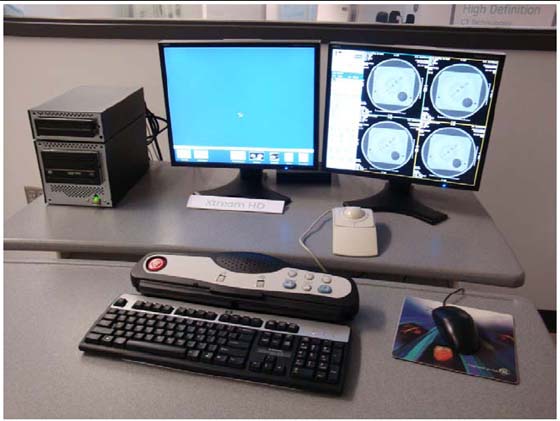
Even if the components look different, the connections are the same.
2 SCIM, Keyboard, Trackball and Mouse Installation for GOC6 Console (On Lean Cart in the desktop component tray)
-
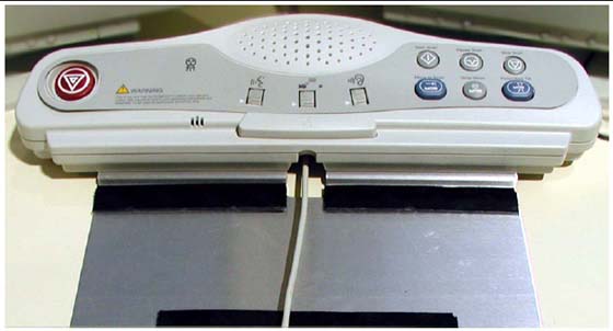
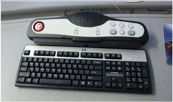
Route the keyboard cable under the SCIM, as shown in Figure 3.
Figure 3. SCIM control with keyboard cable routed through SCIM (actual components may vary in color and style)

- notice
-
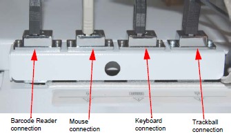
The SCIM, keyboard, trackball, mouse, and barcode reader all have USB connectors that connect in the rear bulkhead on the console as shown in Figure 4.
-
The SCIM, keyboard, mouse, and trackball colors may be different than those shown in this direction. Their installation, connection, and operation is the same.
-
The Media Tower connects using three USB cables in place of the SCSI cable. The optional MOD drive is connected with a USB cable, and can be placed on top of the media tower for easy access.
-
Power cords for all desktop components connect directly to the left rear power bulkhead. All power cables are shipped with the console. Desktop components cables cannot be extended or replaced.
note:Return all shipping boxes and packing materials, including unused monitor cables. Place this material back on the lean cart. All installation packaging should be placed on the cart and returned with the dollies.
Figure 4. Global Console Front Bulkhead, showing mouse, keyboard, barcode reader and trackball connections
-
Connect the SCIM cable to the SCIM as shown in Figure 5. (Note the cable routing.)
Figure 5. SCIM bottom, showing cables and keyboard mounting bracket
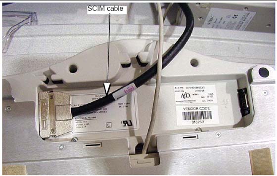
-
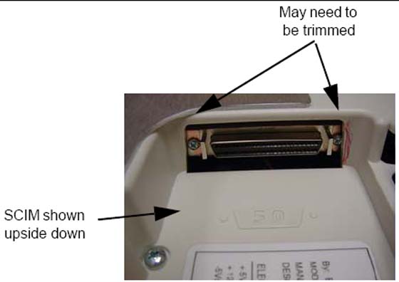
Make sure the SCIM connector fits snugly. Some plastic molding may need to be removed to allow the cable to fit properly.
Figure 6. SCIM Connector Area
-
Select and install the proper keyboard overlay for your system: (1) with tilt or (2) without tilt.
Verify that none of the buttons get caught and stuck under the overlay. Pay close attention to the prescribed tilt button on systems with the tilt feature.
-
The keyboard should attach to the SCIM using the supplied Velcro strip and fit snugly against the SCIM when finished, as shown in Figure 3 and Figure 7.
Figure 7. SCIM connected to the keyboard with the US English tilt overlay installed (actual components may vary in color and style)
3 Connecting the Media Tower for GOC6 Series Console (On Lean Cart in the User Tower & Accessories)
-
Connect the three USB cables to the rear of the media tower. Each USB Cable is labeled, plug the labeled cable end into the correct connector.
note:The cables are included with the console.
-
Connect the power cable to the rear of the media tower.
4 Optional MOD Drive for GOC6 SeriesConsole
Includes both GOC6 and GOC6.5
-
The power and SCSI cables are supplied with the option.
-
Mount MOD drive on top of the media tower.
-
Connect the short power cable from the media tower to the MOD drive.
-
Remove the GOC6 rear cover to gain access to the HP.
-
Locate Channel 1 on the HP.
-
Connect the SCSI cable to channel 1 and route the cable so that is comes out of the top of the console.
-
Reinstall the console rear cover and connect the SCSI to the rear of the mod drive.
5 Connecting the LCD Monitor
With the monitor and computer switched off, connect the video signal cable to the monitor’s video input.
|
Connect the following:
SCIM:
-
SCSI cable from the console
-
Template overlay (Figure 7)
-
Keyboard (see Figure 7)
-
Route cable under the desk top
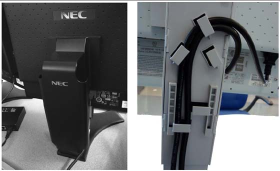
Scan Monitor:
-
Video cable from console
-
Power cable J2
-
Route through the cable keeper
Display Monitor:
-
Video cable from console
-
Power cable J3
-
Route through the cable keeper
Figure 9. Connecting the LCD Monitor
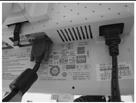
Figure 10. Cable Routing and Keeper
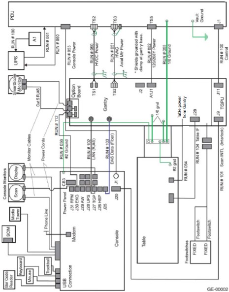
6 Power Panel Connections for GOC6 Series Console
|
|
-
Connect the console power cable to the console power panel.
-
Connect console component power cords as listed in Table 1. Plug LAN cables into the rear bulkhead on the console as shown in Figure 12.
The DIP signal cable is keyed to fit only one way.
The console is not shipped with all external power cables connected to their assigned power slots. Connect the monitor and media tower power cables as shown in Figure 12.
7 GOC6 Console Connections
-
Plug cables into rear bulkhead on console.
Figure 11. GOC6 Console Rear Bulkhead
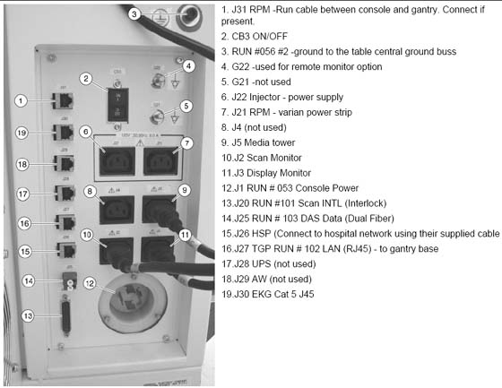
-
System cable connections are located on the rear of the GOC6 console. Connect as shown in Figure 12 below.
Figure 12. GOC6 Series Console Power Connections
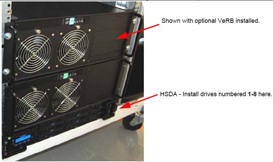
8 Install Drives for GOC6 Series Console
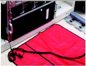
8.1 Tools and Test Equipment
Active static mat and ground wrist strap
|
Figure 13. ESD Mat
8.2 Procedure
Locate the four boxes on the lean cart containing the drives, and place near the console.
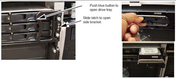
Figure 14. Hard Drive Installation
-
On each side of drive rack are brackets blocking some of the tray access. Slide the latch to release side bracket. Press the blue button on the front to open the drive tray front cover.
Figure 15. Releasing the drive trays
-
With the ESD mat connected and the wrist strap on, remove each drive from the cardboard shipping box. Remove each drive from the static bag.
-
Notice each drive is labeled with a number. This number corresponds to the drive tray location for installation.
Figure 16. HSDA Drive slots replication
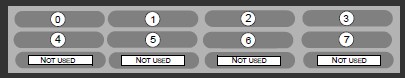 note:
note:Some drives bays have blank trays installed. Do not remove filler plugs or install drives in these four slots.
-
Use the Illustration as reference for drive location, install the 8 drives into the corresponding drive rack.
-
Insert drive into tray and push drive firmly until it "clicks" into place. Repeat for each drive.
note:If the drive fails to click into place, remove the drive by pushing the blue button to raise the door, and then restart the installation process.
-
Close the door and the side brackets to secure the drives after installation.
-
Replace all static bags into the boxes and return the boxes to the lean cart.
9 Optional VeRB Computer Installation on GOC6 Series Console
9.1 Mount the Computer to the Console
-
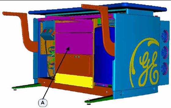
At the front of the console, remove the Rack Blank Panel immediately above the DIG Computer. See Figure 17 (A).
note:Save the four (4) 5mm socket cap bolts and washers.
-
The Rack Blank Panel is no longer needed, dispose of properly.
Figure 17. Rack Blank Panel
-
Remove the VeRB Computer from the shipping container and check that all packaging material has been removed and not blocking intake fans or ventilation grills on the chassis.
-
Lift and slide the computer on to the two rack guides already installed in the console rack.
-
Push the computer fully into the console rack until it is flush with the front of the console rack.
note:If necessary, utilize lifting tools found in the CT Service Manual Safety chapter.
-
Mount the computer to the console rack utilizing the four (4) 5mm socket cap bolts and washers removed from step 1 of this procedure. Torque to 4 N-m.
9.2 VeRB Power Cable Connections
-
On the backside of the console, plug in the computer power cable (p/n 5314704) into the computer outlet. See (C) in Figure 18. Label this end of the power cord "VeRB" using supplied cable labels (p/n 5316747-3) Also check, and if necessary turn ON the computer power switch. See (D) in Figure 18.
Figure 18. VeRB Computer Connections
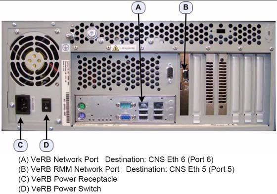
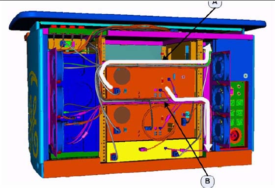
Figure 19. Power cable tray (A) and Network cable tray (B)
-
Run the power cable along the cable tray, directly above the VeRB computer to the right side. See Figure 19.
-
Using the cable labels, place "VeRB J13" label on other end of the power cord. Insert this end of the computer power cable into the console cabinet, along the right side top of the rack, to the Power Distribution Box. See Figure 19.
-
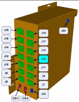
Plug the newly labeled end of the power cord into the J13 on the Power Distribution Box. See Figure 20.
Figure 20. Power Distribution Box Connections (J13)
9.3 VeRB Network Cable Connections
-
On the backside of the console, plug in the VeRB computer network cable (p/n 5313765) into VeRB network port (A). See Figure 18. Place "VeRB Eth 6" label on this end of the network cable.
-
On the backside of the console, plug the other VeRB computer network cable (p/n 5313765) into the VeRB RMM network port (B). See Figure 18. Place "VeRB RMM Eth 5" label on this end of the network cable.
-
Run the network cables along the cable tray, directly below the VeRB Computer, to the right side. See Figure 19.
-
Label the other end of the "VeRB Eth 6" cable "Port 6". Insert this end of network cable into the console cabinet, along right side bottom of the rack, to the Console Network Switch (CNS). See Figure 19 for routing.
-
Label the other end of the "VeRB RMM Eth 5" cable "Port 5". Insert this end of the computer network cable into the console cabinet, along the right side bottom of the rack, to the Console Network Switch (CNS) See Figure 19 for routing.
-
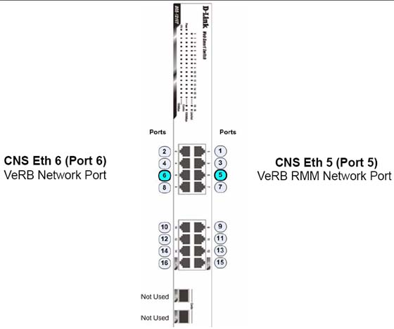
Connect the VeRB Network cables into their respective ports on the CNS. See Figure 21.
Figure 21. VeRB Network Cables Connections on Console Network Switch
-
Using several tie wraps, secure the VeRB power and network cables to the cable trays where they have been routed.
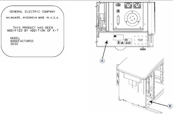
9.4 "Modified By" Kit Plate Installation
Attach the VeRB "Modified By" kit plates (p/n 5335238) along side the present Rating Plates in the following locations. See Figure 22.
-
(A) Backside of Console, near Rear Bulkhead Panel
-
(B) Inside the console near Power Distribution Box
Figure 22. Modified By Kit locations and label example
10 Optional USB Barcode Reader
-
Locate the barcode reader box on the lean cart options section.
-
Connect the USB cable to port USB A on the back of the console
-
Dress any excess cable and place under the monitor desktop.