- Topic ID: id_15460651
- Version: 2.0
- Date: Nov 8, 2018 1:36:22 AM
Console Cable Connections - GOC5
1 Monitor Location
-
Locate and unpack the two monitors from the lean cart (see Figure 1).
Figure 1. Lean Cart Layout
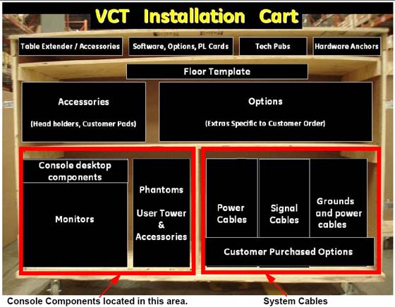
-
Carefully place the monitors on the console desktop.
-
Locate and unpack the media drive tower.
-
Place the media tower on the console desktop.
2 Monitor and SCSI Tower Placement for GOC5 Console
-
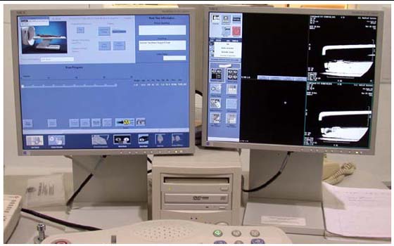
Locate and unpack the two monitors.
-
Carefully place the monitors on the console desktop.
-
Locate and unpack the SCSI drive tower.
-
Place the SCSI drive tower on the console desktop.
Figure 2. GOC5 Global Console tabletop Component Placement
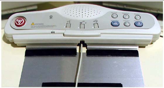
3 SCIM, Keyboard, Trackball & Mouse Installation for GOC5 Console
-
Route the keyboard cable under the SCIM, as shown in Figure 3.
Figure 3. SCIM control with keyboard cable routed through SCIM (actual components may vary in color and style)

- notice
-
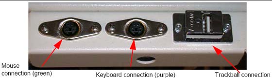
Connect the keyboard and mouse to the ports on the top of the console front bulkhead. The keyboard connects to the port on the right; the mouse connects to the left port (Figure 4).
Figure 4. Global Console Front Bulkhead, showing mouse, keyboard, barcode reader and trackball connections
-
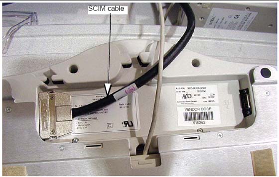
Connect the SCIM cable to the SCIM as shown in Figure 5. (Note the cable routing.)
Figure 5. SCIM bottom, showing cables and keyboard mounting bracket
-
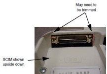
Make sure the SCIM connector fits snugly. Some plastic molding may need to be removed to allow the cable to fit properly.
Figure 6. SCIM Connector Area
-
Select and install the proper keyboard overlay for your system: (1) with tilt or (2) without tilt.
Verify that none of the buttons get caught and stuck under the overlay. Pay close attention to the prescribed tilt button on systems with the tilt feature.
-
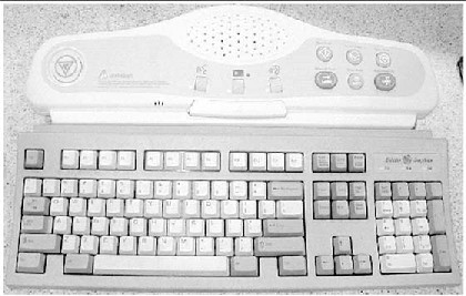
The keyboard should attach to the SCIM using the supplied Velcro strip and fit snugly against the SCIM when finished, as shown in Figure 7.
Figure 7. SCIM Connected to Keyboard with US English Tilt Overlay Installed
4 Connecting the SCSI Tower on GOC5 Console
Figure 8. SCSI Tower: Connections (left) and Optional Seismic Mounting Bracket (right)
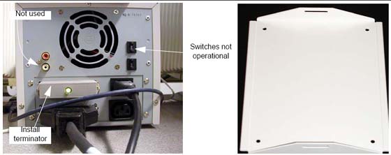
-
Connect the SCSI cable to the rear of the SCSI tower.
note:The cable is included in the SCSI Cable Kit and is the same as the DASM cable.
-
Connect the SCSI terminator to the rear of the SCSI tower.
-
Connect the power cable to the rear of the SCSI tower.
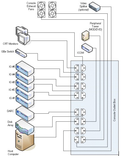
5 Connecting the LCD Monitor
With the monitor and computer switched off, connect the video signal cable to the monitor’s video input.
|
Connect the following cables:
SCIM
-
SCSI Cable
-
Template
-
Keyboard
Scan Monitor:
-
Video Cable
-
Power Cable
-
Cable Keeper
Display Monitor:
-
Video Cable
-
Power Cable
-
Cable Keeper
A DARC video cable is shipped with the system. This is only to be connected when troubleshooting. Do not connect during normal installation.
6 Power Panel Connections for GOC5 Console
|
|
-
Connect the console power cable to the console power panel.
-
Connect console component power cords as listed in Table 1. Plug LAN cables into the rear bulkhead on the console.
The DIP signal cable is keyed to only fit one way.
“J” numbers increment from top to bottom and left to right.
The console is shipped with all internal power cables connected to their assigned power slots.
7 GOC5 Console Connections
-
Plug cables into rear bulkhead on console.
Figure 9. Console Rear Bulkhead
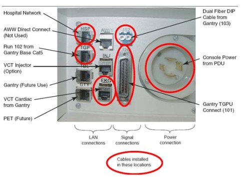
-
System cable connections are located on the rear of the console. Connect as shown in Figure 10 below.
Figure 10. GOC5 Console Power Connections
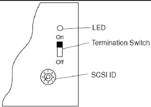
8 Installing a DASM (Hardware Option for GOC5 Console)
If you have a digital DASM to install, complete the following steps to connect it to the computer.
-
Turn the DASM over so you are looking at the bottom.
-
Set the DASM SCSI ID to 1.
-
Set the DASM termination to ON.
Figure 11. DASM Bottom
-
Set the RS232/RS422 switch to the RS232 position, for a digital DASM.
-
Refer to Figure 12. Attach the SCSI cable supplied with DASM kit to the back of the DASM.
Figure 12. Rear View of HP xw8000, Showing DASM SCSI Cable Connection
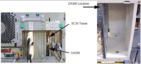
-
Attach the free end of the SCSI cable to the rear of the Host Computer (see Figure 12).
-
Plug DASM power cord into J10 (or any open slot).
-
Attach remaining cable(s) from camera to DASM and install the DASM to the right of the slideout tray.
See your Software Load Procedures manual for instructions on configuring cameras.
9 GOC5 Console Modem Option
A signed deviation is required to install the modem option.
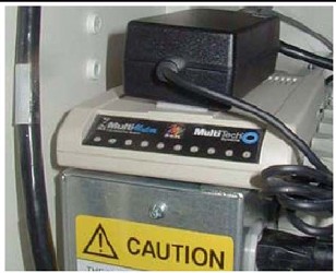
If you have a modem to install, do it now. Place the modem on top of the intercom box and attach it with Velcro to the power supply.
Hook up the power, phone, and serial line as shown in the interconnect drawing. The drawing is located in the back cover of the console.
Figure 13. Modem
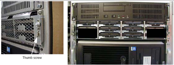
10 Install Drives on GOC5 Console
|
Install drives in the eight (8) slots shown in Figure 14 as follows.
-
Using the thumb screws, remove the front cover. Use caution so you do not damage the tabs on the top edge or the small plates on the bottom edge.
-
Remove the cardboard shipping box with slots for eight drives on the right side of the console.
-
Install eight drives in the open slots. They snap into place.
-
Replace the box with the installed drives.
-
Using the thumb screws, replace the front cover.
Figure 14. Hard Drive Installation