- Topic ID: id_18480282
- Version: 3.0
- Date: Jan 20, 2020 8:36:15 PM
Tilt Potentiometer Replacement
Prerequisites
Overview
Procedure Effectivity:
Procedure
- Remove all covers except rear cover. All work should be performed from the left, front corner.
- Stop the rotor of X-ray tube in case of Liquid Bearing Tube before HVDC off. Refer to Liquid Bearing Tube Rotor stop procedure for details.
- Turn off the Axial Drive and HVDC switches on the gantry’s Service Switch Panel.
- Turn off the 120VAC switch.
- Perform all required LOTO activities.
- Loosen the two (2) hex screws that mount the Tilt Potentiometer to the gantry assembly.
- Remove the belt from the 32-tooth pulley on the Tilt Pot Assembly.
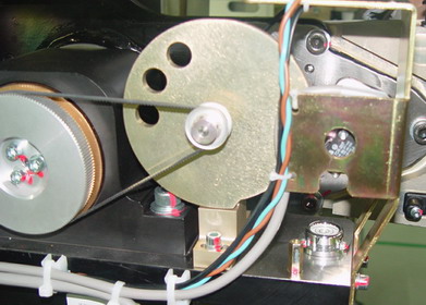
- Remove connectors from the Tilt Pot Assembly (Illustration 1).
Figure 1. Gantry Tilt Pot Assembly
- Remove two (2) hex screws that secure the Tilt Pot Assembly.
- Remove the Tilt Pot Assembly.
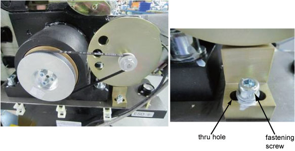
- Ensure the fastening screw should be located at the center of
thru hole on the bracket.
- Reverse the above steps to install the new Tilt Pot Assembly.
- Perform Tilt Characterization.
Finalization
No finalization steps.