- Topic ID: id_18718306
- Version: 1.1
- Date: Aug 18, 2020 3:38:47 AM
Table Elevation Actuator Replacement
Prerequisites
Overview
Procedure
- Raise the table to maximum height.note:
Remove all objects from the cradle before proceeding.
note:The gas spring shocks have sufficient lifting force to drive and hold the table top to its maximum height. Make sure to install the Gas Spring Block Service tool or a wood block of sufficient mass to act as a secondary safety device before removing the actuator.
- Remove the right Gantry Side Cover.
 warning
- notice
- Remove power from table by turning off 120VAC, Axial Drive and HVDC switches on Service Switch Panel.
- Remove the Table Base Covers, the Side Covers, the right Side Rails and the Actuator Cover.
- Remove the Actuator Cover U-bracket and crossbar.note:
As you disconnect the wires in the next step, remember or note the locations of the motor wire terminals because you have to replace them in the same position later.
- Disconnect the motor wires, ground strap, and limit switch wires.
- Cut the Tie-Wraps, and remove the clamp that fastens the limit switch wires to the Actuator.
- Remove tension from the Actuator:
- Raise the table past its upper height limit by manually turning the hex drive on the end of the motor.
- Raise the table to fully extend the gas springs, while the lower gas spring remains at the back of the slot in the lower mounting block.
- The Gas Springs should just barely be engaged.
(Remove covers as necessary to gain access to the actuator.)
- warning
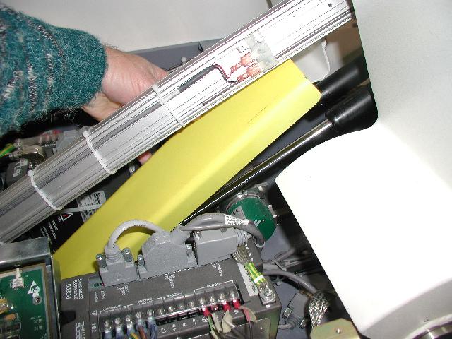
- Insert the Gas Spring Block Service tool as shown in Figure 1.
Figure 1. Gas Spring Block Service Tool PN# 2144261
- Loosen and remove the lock nut from the upper Actuator mounting pin.
If you cannot easily remove the upper Actuator mounting pin, return to the
previous step, and raise the table to remove the gas spring tension.note:
It is important to loosen both actuator-mounting pins before you remove either one.
- Pay attention to the positions of the two bumper washers and spacer when you remove them.
- Retract the Actuator manually with the hex drive, but do not let the
Actuator fall when the rod end clears the upper mounting block.note:
Do not over-shorten the Actuator.
- Remove, and keep, the E-ring from the lower mounting pin.
- Slide the pin out.
- Lift and remove the Actuator from the table.
- When you install the Actuator:
- Coat the lower pin with a thin layer of Molykote grease.
- Take care to install the E-ring correctly.
- Place one bumper washer on each side of the rod end of the Upper Mounting
Pin.
-
On the right side, the bumper washer fits over the shoulder on the hex-side of the pin.
-
On the left side, the spacer fits inside the bumper washer, and spaces the rod end away from the mounting clevis.
-
- Connect the motor wires to the corresponding terminals as noted earlier.
- Connect the wires to the limit switches of the actuator (both upper and lower).
- Tie-Wrap the limit switch harness in place.
- Remove the Gas Spring Block Service Tool or wood block or both.
- Power on the system and adjust the Lower and Upper Actuator Limit Switches to be set at 369mm and 854mm from the Characterization Plate, respectively.
- Reassemble the Actuator Cover.
 |
Finalization
-
- notice
- Power up the Table from the Service Switch Panel.
- Follow the procedure on Table Characterization to Characterize the Table Elevation.
- Using the service switches on the MTCB, move the Table up and down, and the Cradle in and out.
- Use the gantry control keys to move the Table up and down, and the Cradle in and out.
- When the Table functions properly, reinstall the Table Base Covers, the Side Panels and the Gantry Side Cover.