- Topic ID: id_16157919
- Version: 3.0
- Date: Jun 10, 2020 2:42:14 AM
Pancake DAS DDIF Cleaning Procedure
Prerequisites
Overview
The following procedure should be followed when DAS converter boards and/or chassis need cleaning, or converter boards are replaced for microphonics or noise, resulting in image artifacts (rings, bands, streaks, and smudges).
Procedure
- The following steps are to be performed only if:
-
Image Quality or DAS 16 performance issues are present.
-
Extremely dusty or dirty room environment is present.
-
- Take DC Noise and DC Offsets baseline scan using DASTOOLS Manual test (use default settings) to establish the current noise characteristics of DAS. Do not troubleshoot any noise failures until after the cleaning.
- Use the DASTools Viewlog to view the results of the baseline noise test to see the channels that violate the noise specification. The specifications are shown next to the actual data for the failed channels and shows the converter card number.
- Position the table to its lowest position.
You will be sitting on the edge of the cradle to work on the DAS.
- Remove gantry right side cover, and turn OFF all three (3) service
switches.
Refer to
- Continue to open the gantry, by removing applicable gantry covers.
Refer to
- Turn off all three switches (Axial Drive, HVDC, 120VAC).
- Lock the gantry in position, using the rotational lock.
Refer to “Rotational Locking Pin” within Equipment Service - Gantry, located in the Safety tab of this publication, for details.
- All protective ESD materials should be in place (i.e. wrist straps, Nitrile gloves, Amax, and Aero Duster; ionizing fan set up at far end of the patient table).
- Remove Pancake DAS covers. Follow the procedure of Pancake
DAS covers removal.
Perform general cleaning procedure on air plenum as outlined in Pancake DAS General Cleaning.
- notice
- Use assembled Aero Duster spray and nozzle, blow off the dust. Pay particular attention to the spaces between the Flex connections.
- Use Ionizing fan to remove any built-up charges.
- notice
- notice
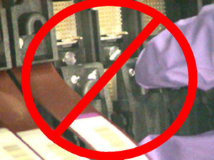
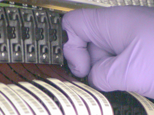
- Using the Flex Extraction Tool, disconnect both A and B flexes
from the DDIF. See Figure 1 and Figure 2. Refer to DAS 16 DDIF Tools for details on the Flex Extraction Tool.
-
Disconnect the failing flexes identified in your analysis and each adjacent flex.
-
Disconnect both inner and outer flexes.
-
Connect the special flex grounding straps provided in the DAS/Detector Kit shipped with the system.
Figure 1. "A" Row Flex Removal and Work Clearance
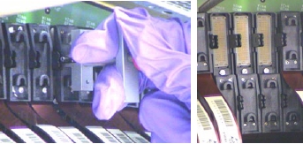
Figure 2. "B" Row Flex Removal
-
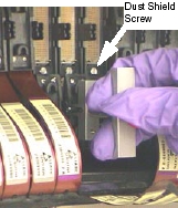
- Remove the Dust Shield after both flexes have been disconnected.
-
Use the provided screwdriver bit found in the DAS/Detector Service kit.
-
Remove any metal particles that might be magnetically attached to your screwdriver.
-
- Using the Interposer Removal Tool, remove both Interposers.
Refer to DAS 16 DDIF Tools for details on the Interposer Removal Tool.
-
Inspect Interposers with a magnifying glass.
-
Look for bent or broken pins.
-
If broken pins are observed and found lodged in the female connector, go to “Broken Interposer Pin Removal,” in Interposer Replacement.
-
- Using the magnifying glass, inspect the Dust Shield Retainer
Clip.
-
Look for chipped or broken corners.
-
If chips are observed, inspect the immediate area for the missing chips. Remove these chips as this can result in microphonics noise.
-
If retainer clip is cracked or severely damaged, go to “Dust Shield Retainer Clip Replacement,” for replacement instructions in Interposer Replacement.
-
- notice
- notice
- Using Amax spray cleaner, spray away from the detector toward
the DAS chassis.
-
Position the DAS at 6 O’clock.
-
Carefully bend the flex leads out of the way. A ratchet extension works well to prevent creasing of the flex. See Figure 3.
-
Use lint free cloth to absorb excess AMAX and protect DAS Chassis. See Figure 3.
-
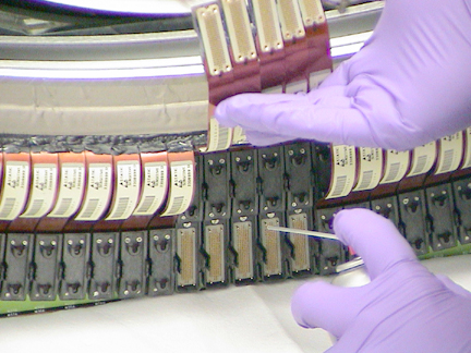
Support flexes with one hand and spray AMAX with the other. See Figure 4.
-
Allow Amax to fully dry before assembly.
Figure 3. DDIF Flex Handling
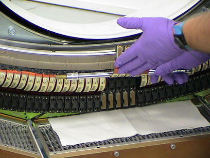
Figure 4. DDIF Cleaning with AMAX
-
- Use Amax spray cleaner to clean the interposers.
Allow Amax to fully dry before assembly.
- Use the Ionizing Fan to remove any built-up charge in the area.
- Carefully install the interposers using your Nitrile glove protected fingers.
- Install the Dust Shield.
-
Use the screwdriver bit provided in the DAS/Detector Service kit. Torque to: [0.35 Nm, 3 in-lbs, 3.6 kg-cm].
-
Remove any metal particles that might be magnetically attached to your screwdriver.
-
Do not over tighten the fastener.
-
- Install the flex leads using your Nitrile glove protected fingers.
- Assemble the rest of the gantry.
- Restore power.
-
Perform general cleaning procedure on air plenum as outlined in Pancake DAS General Cleaning if not done as directed at the beginning of this procedure.
-
It takes two minutes of warm-up time for every minute the DAS was turned off, up to one hour. The DAS can be warming up while the Air Plenum is being cleaned, before performing Fastcal or Image Quality testing.
-
- Perform Image Quality testing.
 |
|
|
|
|
Finalization
No finalization steps.