- Topic ID: id_16157893
- Version: 3.0
- Date: Nov 27, 2020 2:16:55 AM
PDAS Control Board (DCB) Replacement
Prerequisites
Overview
1 Board Removal
Procedure
- notice
- Position the table to its lowest position.
- Remove the gantry right side cover.
- notice
- Turn OFF Axial Enable, HVDC, and 120VAC switches on the Service Switch panel.
- Remove the gantry top and front covers.
- Position the DAS at the 12 o'clock position.
- Lock the gantry in position using the rotational lock.
- Disconnect all cables on IFB cover. One is Fiber Optic Cable, the other is fan power cable.
- Loose the three screws, remove 6 x M6 hex screws from the IFB
cover. See Figure 1
Figure 1. Screws on IFB Cover
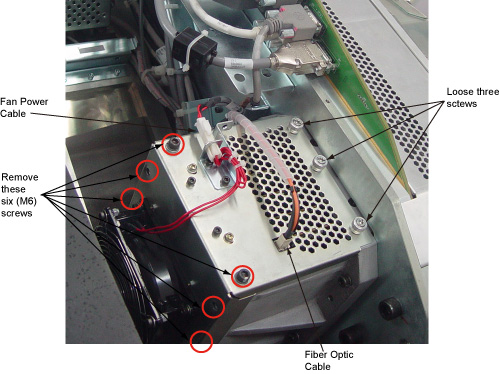 note:
note:Do not touch any other screws on the IFB Cover.
- Slide the IFB cover.
- Put on wrist strap and use ESD precautions.
Figure 2. DCB Board removal
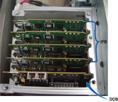
- Slide the DCB out of chassis and place into anti-static bag.
 |
|
2 Board Installation
Procedure
- notice
- Get new DCB from anti-static bag.
- Align DCB edges to board guides in Chassis.
- Slide the board into the chassis and push board into place.
- Install the IFB cover into place
- Secure all the screws. Torque M6 hex screws to 7.9N-m.
- Reconnect fiber optic cable and fan power cable.
- Disengage the rotational lock.
- Turn on Axial Enable, HVDC, and 120VAC switches.
3 Finalization
Procedure
- Perform Flashdowload.
- Perform Z-Slop
- DAS Gain Calibration
- FastCal
- Verify proper functionality:
- Run at least 10 passes of Scan Data Path Diagnostic.
- Take 10 I/Q scans of the 48cm phantom.
- Verify fault or reason to replace the board now passes.
- Reassemble gantry covers.