This procedure describes and illustrates the steps necessary
to install the Option MOD Peripheral Tower.
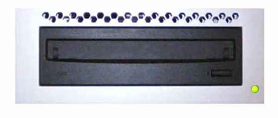
Figure 1. MOD Peripheral Tower
1 Power-Off (Shut Down) the Console
Procedure
Select one of the following methods to power off the Operator
Console:
If applications are running, click
the Shut Down icon and select Shut
Down.
If applications are down, open a Unix
Shell using the Toolchest. Type: {ctuser@hostname} halt. Press Enter.
The Operator Console monitor will display a ‘System Halted’
message when it is acceptable to power off the Operator Console.
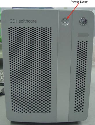
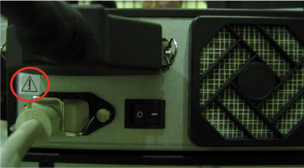
Power OFF the Operator Console at the front panel switch. (See Figure 2.)
Figure 2. Console Power Switch
2 Install Option MOD Peripheral Tower
Procedure
Install the Option MOD Peripheral Tower chassis on the Operator
Console.
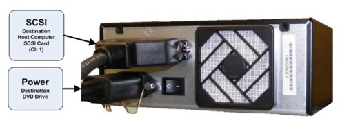
Mount the power cord to the rear of the MOD Peripheral Tower
chassis. Verify that the power switch on the MOD Peripheral Tower
Power Supply is turned to the ON position.
Make sure the rear SCSI cable connections.
Figure 3. MOD Peripheral Tower Connections
3 Power-On the Operator Console
Procedure
Power ON the Operator Console at the console front panel switch.
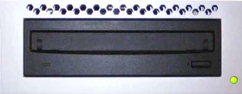
Visually verify the MOD Peripheral Tower front panel Power LED
is illuminated.
Figure 4. MOD Peripheral Tower Power LED
4 Verify Install MOD Peripheral Tower Operation
Procedure
Visually verify the Peripheral Tower front panel Power LED is
illuminated and that each of the MOD Drive Access LEDs illuminates
when media is inserted and the tray is closed.
No other verifications required.
5 Attach Label on MOD Tower
The label Part Number is 5346627. It is shipped with TIO Console,
not in the Option kit. So please find the label from the TIO Console
package. Paste the label behind the MOD Tower, proper location refer
to Figure 5
Figure 5. MOD Tower Label
Only trained GE personnel should be install and
service the power connection of the MOD Tower.