- Topic ID: id_18718169
- Version: 1.0
- Date: Sep 20, 2018 2:02:31 PM
Intercom Board Replacement
Prerequisites
Overview
This module describes the procedures used to replace the Intercom Board in:
-
GOC4 Console
-
All-In-One Console
After the Intercom board has been replaced and, several tests and adjustment are required:
-
Console and table speaker volume adjustment
-
Prescribed tilt function test
1 Power-Off (Shut Down) the Console
Procedure
- Select one of the following methods to Power OFF the Operator
Console:
- If Applications are up, click on the Shut Down button and select Shutdown.
The Operator Console monitor will display a 'Power Down' message when it is acceptable to power OFF the Operator Console.
- If Applications are down, open a Unix Shell. Type: halt.
- If Applications are up, click on the Shut Down button and select Shutdown.
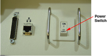
- Power OFF the console at the front panel switch.
Figure 1. Power Switch
2 Remove the Old Intercom Board
Procedure
- Remove the front Operator Console covers.
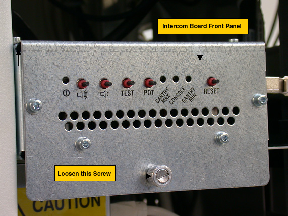
- Loosen the screw located on the front panel of Intercom Board,
which secures Intercom Board to the chassis. note:
You do not need to remove this screw.
Figure 2. Intercom Board Front Panel
- Slide the Intercom Board out of the console to approximately
half position.note:
Be careful of the cables connected on the Intercom board.
- Visually verify proper labeling of each cable and disconnect
all cables on the right side panel. If necessary, add a label to each
cable for clarity.
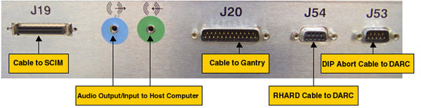
Cables to be removed: (Refer to Figure 3 below for cable connections)
-
J19: Cable to SCIM/Keyboard
-
Audio output/input cable to Host Computer, connect as per the color of the cable adapter
-
J20: Cable to gantry
-
J54: Serial RHARD cable to DARC
-
J53: Serial DIP Abort cable to DARC
-
Power cord on the rear panel
Figure 3. Cable Connection on GOC4 Intercom Board Right Side Panel
-
-
(For All-In-One console (no DARC)) Refer to
instructions below for cable connections:
-
J19: Cable to SCIM/Keyboard
-
Audio output/input cable to Host Computer, connect as per the color of the cable adapter
-
J20: Cable to gantry
-
J54: Serial RHARD cable to HP Host Computer
-
J53: Serial DIP Abort cable to HP Host Computer
-
Power cord on the rear panel
-
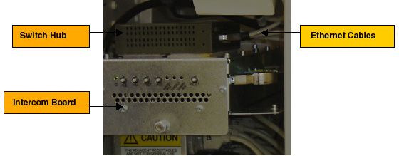
- (For Consoles with Switch Hub) Remove Switch Hub from the Intercom Board:
- Slide the Intercom Board all the way out of the Console.
- Remove five (5) Ethernet cables from the Switch Hub. Add a label
to each Ethernet cable if necessary, as shown below:
Figure 4. Ethernet Cables
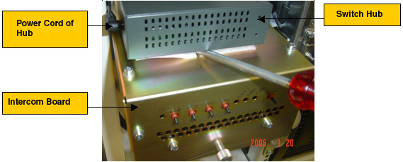
- Remove the Switch Hub power cord at the rear panel, then remove
the Switch Hub from the Intercom Board. A screw driver can be used
if it is difficult to remove the Switch Hub, as shown below:
Figure 5. Switch Hub Power Cord
- Take the Switch Hub out of the Console.
- Remove five (5) Ethernet cables from the Switch Hub. Add a label
to each Ethernet cable if necessary, as shown below:
3 Install the New Intercom Board
Procedure
- Slide the replacement Intercom Board into the Console.
Re-Connect the cables as using Figure 3 above as a guide. At the rear panel of Intercom Board, verify the power switch is in the “ON” position, and connect the power cord.
- (For Consoles with Switch Hub) Attach the switch hub on the new Intercom Board. Re-connect five (5) Ethernet cables and power cord.
- Push the Intercom Board all the way into the console and tighten the screw at the front panel of the Intercom Board.
4 Power On the Console
Procedure
- Power ON the Operator Console at the front switch panel.
5 Intercom Board Adjustment / Test
Procedure
- Adjust the console and table speaker volume; refer to GOC4 Intercom Theory and Adjustments.
- Take some scans which need to do prescribed tilt; verify the prescribed tilt function is normal.
6 Finalization
Procedure
- Install the console front cover back.