- Topic ID: id_16157867
- Version: 4.0
- Date: Jan 20, 2020 8:36:28 PM
Hydraulic Return Hose Replacement
Prerequisites
Overview
Procedure
- Raise the Table to maximum height.
- Perform this step if applicable:
(For Global PET/CT Table, with fixed position IMS) Move the Cradle to OUT limit position.
(For Global PET/CT Table) Move the Cradle and IMS to OUT limit position.
(For GT1700 and GT2000 Table) Move the Cradle and IMS to OUT limit position.
(For GT1700V Table) Move the Cradle to OUT limit position.
- Remove power from Table by turning off 120VAC, Axial Drive and HVDC switches on Service Switch Panel.
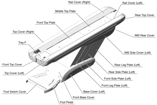
- Remove the following Table covers:
-
IMS Rear Cover
-
IMS Side Cover Right/Left)
-
Front/Rear Side Plate (Right/Left)
-
Front/Rear Leg Plate (Right/Left)
Figure 1. Table Covers
-
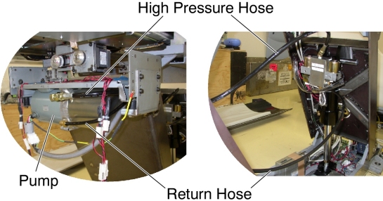
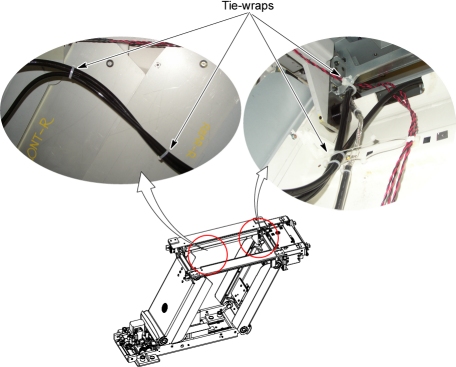
- Cut any tie-wraps holding the Return Hose.
- Disconnect the Return Hose from the hydraulic cylinder. A oil may spill out from the hose. Drain oil in the hose.
- Disconnect the Return Hose from the hydraulic pump.
Figure 2. Hydraulic Hoses
- Connect the new Return Hose, one end to the cylinder, and the
other end to the pump, then tie-wrap the hose in place.
Figure 3. Hydraulic Hoses Configuration (GT1700, GT2000 and Global PET/CT Table)
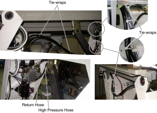
Figure 4. Hydraulic Hoses Configuration (Global PET/CT Table, with fixed position IMS)
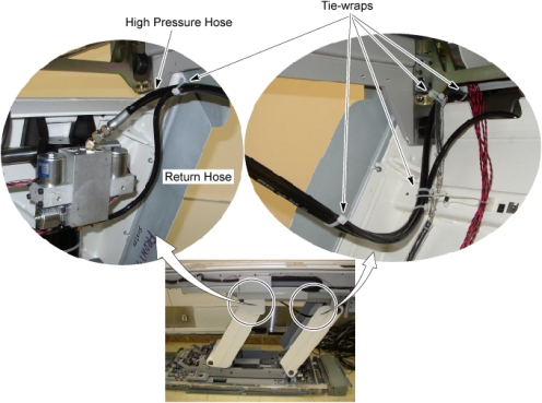
Figure 5. Hydraulic Hoses Configuration (GT1700V Table)
- Table pump lubrication:
- Mark the position of pump upper cover on both sides for re-installation.
- Disconnect the cable connectors of the tape switches and touch sensors.
- Remove six (6) screws holding the both sides of the pump upper
cover, and remove the pump upper cover.
Figure 6. Pump Upper Cover Removal

- Pry a lid up using a flat-head screw driver.
Figure 7. Lid of Pump
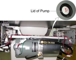
- Pour approximately 100cc of the oil into the pump.
- Power up the Table from the Gantry Service Switch.
- Raise the Table as high as possible.
- Turn off the Table from the Gantry Service Switch.
- Repeat step Step 9.d through Step 9.h until Table height reaches mechanical Up-limit.
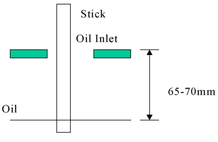
- Check the level of the oil by using a stick such as tie-wrap,
specification is shown in illustration below.
Figure 8. Check Oil Level
Finalization
- Secure any loose hoses with tie-wraps.
- Raise and lower the Table repeatedly to verify that the hoses do not catch or pull excessively.
- Turn off all 3 switches (Axial Drive, HVDC, 120VAC), and re-install the Table covers.