- Topic ID: id_18718327
- Version: 2.1
- Date: Sep 28, 2020 2:51:22 AM
HP Host Computer CDIP/CDIP2 Board Replacement
Prerequisites
Overview
1 Power OFF (Shut Down) the Console
Procedure
- If Applications are up, click on the Shut Down button.
- Power OFF the Operator Console front switch, when instructed to “Power Down”.
- Remove the rear Operator Console cover.
- Visually verify proper labeling of each cable and disconnect
all HP Host Computer rear cables.
(Refer to schematic for HP cable connection details - click on PDF icon, 2090969.pdf, to view PDF version.)
- Remove the front Operator Console cover.
- Remove and retain the four (4) front mounting screws.
 caution
- Slide out the HP Host Computer module.
2 Remove the Side Cover
In All-in-One console, CDIP/CDIP2 board is installed in HP host computer. Before CDIP/CDIP2 board replacement, need to open side cover of HP host computer at first. With ALL cables removed from the old and new Host Computers, perform the following steps:
Procedure
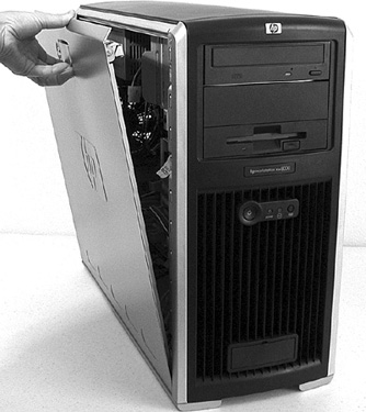
- Unlock the cover on the side of the old Host Computer.
The cover keys are attached to the back panel of the system.
- Pull out on the side cover latch to release the side cover.
- Tilt the cover open, then lift it off. Refer to Figure 1.
Figure 1. Opening the Side Cover
3 CDIP/CDIP2 board replacement
Procedure
- Locate the CDIP/CDIP2 board in Host Computer. CDIP/CDIP2 board is installed in slot 5.
- Remove the old CDIP/CDIP2 board from Host Computer and install new CDIP/CDIP2 board in the same slot position (slot 5) in Host Computer.
4 Replace the Side Cover
Procedure
- Ensure that all internal cables are properly connected and safely routed in the new Host Computer.
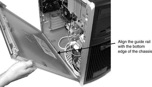
- Place the side cover onto the Host Computer chassis (aligning
the guide rail on the bottom inside edge of the cover with the bottom
edge of the Host Computer chassis). Refer to Figure 2.
Figure 2. Aligning and Closing the Cover
- Verify no cables are pinched, and gently close the cover.
- Lock the cover using the key provided.
5 Install the New HP Host Computer
Procedure
- Slide in the HP Host Computer module.
- Replace the four (4) front mounting screws.
- Reconnect all HP Host Computer rear cables.
- At the rear of the HP Host Computer, verify the power switch is in the ON position.
- Apply power to the Operator Console by turning ON the front switch.
note:
In this case, if CDIP2 replace old CDIP, need replace the fiber cable which from bulkhead to host computer rear panel.
6 Finalization
Procedure
- Take some scans, verify the image(s) reconstruct and are displayed.
- Install the front and rear Operator Console covers.