- Topic ID: id_18718027
- Version: 2.0
- Date: Feb 4, 2020 1:40:32 AM
Gantry Front Cover Removal and Re-Install
Prerequisites
Overview
This procedure explains how to remove and re-install the CT Gantry front cover.
1 Redesigned Front Cover Dolly Setup
Procedure
 danger
- notice
- Arrange Dolly sections for assembly. The base and post can be
assembled only one way. Refer toFigure 1 and Figure 2.
-
The base uses two (2) palm screws to clamp the four (4) legs in the open or usage mode.
-
The base also uses the same palm screws to prevent the legs from falling in storage mode.
-
The top post can be inserted in either base and is keyed for proper engagement.
-
The top post locking pin prevents the sections from separating during usage.
Figure 1. Redesigned Front Cover Dolly in Storage Mode
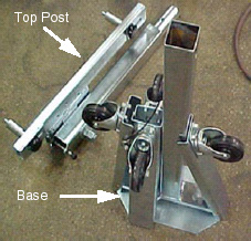
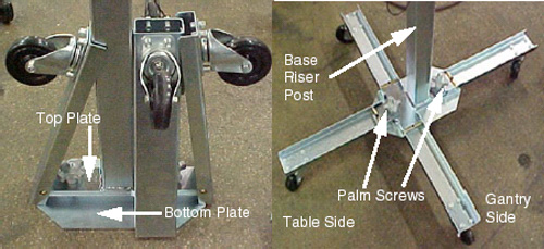
Figure 2. Redesigned Front Cover Dolly Base Assembly
-
- Unfold the base legs by loosening both palm screws to the top of their travel.
- Carefully unfold the legs so that the castors touch the floor.
- Tighten the palm screws to clamp the legs between the base top
and bottom plates.note:
Lifting the base by the riser post while leaving the castors on the floor will ease palm screw tightening.
- warning
- Insert top post into the base riser post. Align the key for complete engagement.
- Insert top post locking pin to secure both top and bottom sections.
- Reverse above steps to disassemble.note:
For base storage only one (1) palm screw needs to be tightened. This will engage the bottom base plate and the leg ends preventing the legs from unfolding during transport and storage.
 |
2 Removal
Procedure
- Position the table at its lowest position.
- notice
- Remove gantry side and top covers, if you have not already done so.
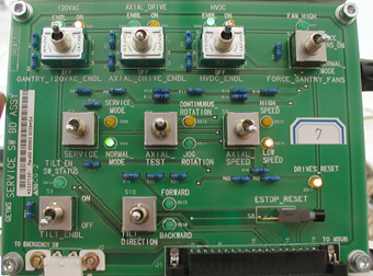
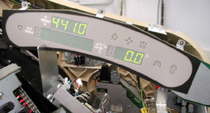
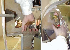
- Verify the three (3) power switches have been turned OFFFigure 3.
Figure 3. Service Switch Panel
- Assemble the front cover dolly.
- Detach front cover J3 and J2 and front cover BKHD J1 cables.
- Remove the Mylar (scan) window.
- Remove front cover.
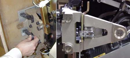
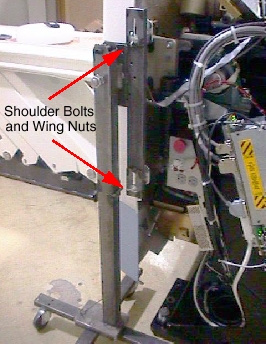
- Disengage upper and lower cantrell brackets on both sides of
the cover.
-
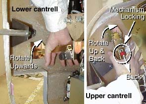
Using steady but firm pressure, lift each of the lower cantrell brackets from their associated retainers. See Figure 5.
Figure 5. Releasing Cover Brackets
-
Disengage the locking mechanism on the upper cantrell brackets by using your thumb to slide the trigger (red lever) back. This will release the locking mechanism and allow the cantrell to be rotated upwards with steady and firm pressure.
-
- Disengage the rubber retaining straps on both sides. See Figure 6.
You may find it helpful to lift “up” on the cover to align
the stud while attaching the rubber retaining straps.
Figure 6. Rubber Retaining Straps and Cover Locking Mechanism
- Lift and rotate cover locking arm to unlocked position.
- Disengage upper and lower cantrell brackets on both sides of
the cover.
- Rotate front cover away from gantry.
- Move front cover away from gantry, leaving space (about 5 feet) between cover and gantry.
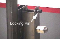
- Pull the locking pin and rotate front cover away from gantry.
Place locking pin in one of the side dolly perforations. See Figure 7.
Figure 7. Releasing Front Cover Dolly Hinge
- Continue cover removal per Figure 8.
Figure 8. Front Cover Removal Sequence
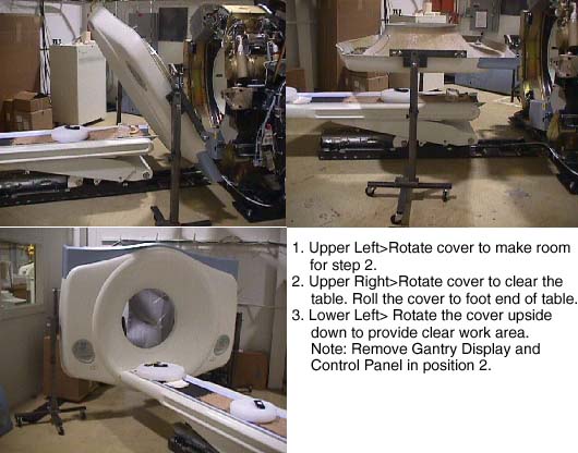
- Rotate the cover horizontally and move it back and over the table to a safe location. Once in a safe location, you may over-rotate the cover full vertically but upside down.
- Remove the gantry display from the front cover and place it
into its service position.
- The gantry display is held in place with (5) thumb screws. Use
a flat-blade screwdriver to remove the Display. See Figure 9.
Figure 9. Gantry Display Removal
- Place the Display in the bracket on the right side of the gantry.
See Figure 10.
Figure 10. Gantry Display Service Mounting Location
- Disconnect the cabling at the right rear gantry cover. Only (1) cable will connect to the Gantry Display. Connect the cable taken from the rear cover to the display.
- The gantry display is held in place with (5) thumb screws. Use
a flat-blade screwdriver to remove the Display. See Figure 9.
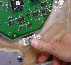
- Remove one (1) of the cover’s control assemblies, and
place it into its service position.
- Press on each ball stud until the panel is released. See Figure 11.
Keep one hand on the control panel at all times to prevent it from
dropping to the floor.
Figure 11. Gantry Control Panel Removal
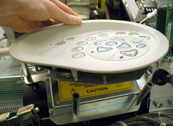
- Align the ball studs with their associated receivers and snap
into place.
Figure 12. Control Panel Service Position
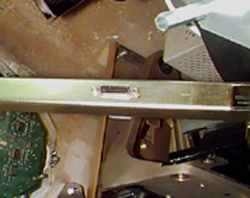
- Connect cable to terminator located on the cantrell arm. See Figure 13.note:
There are 3 cables, each of which is unique. The ribbon cable is not used in the Service configuration. The other 2 cables will only fit in the terminator or the control panel, not both.
Figure 13. Gantry Service Mode Cable Terminator
- Press on each ball stud until the panel is released. See Figure 11.
Keep one hand on the control panel at all times to prevent it from
dropping to the floor.
|
3 Installation
Procedure
- Remove the gantry display and control assembly from their service
positions and reattach them to the gantry cover.
- Disconnect cables from Display and Gantry Control Panels.
- Install Gantry Display in front cover. Secure the 5 thumbscrews. With a flat-blade screwdriver, gently tighten past finger-tight.
- Install the gantry control panel, making sure the ball studs are secure within the receivers.
- Reattach cables.
- notice
- Rotate gantry back to its vertical position.
- Attach the front cover.
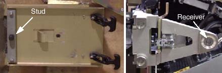
- Align the studs on both sides of the front cover with each associated
receiver. Receiver is located on the gantry frame.
Figure 14. Cover Stud and Mounting Bracket Receiver
- Insert the stud on one side into its associated receiver and
attach the rubber retaining straps.Then insert the stud on the other
side into its associated receiver and attach its rubber retaining
straps.
You may find it helpful to lift "up" on the cover to align the stud while attaching the rubber retaining straps.
- Align the studs on both sides of the front cover with each associated
receiver. Receiver is located on the gantry frame.
- Reattach upper and lower cantrell brackets on both sides.
- Remove upper Cantrell brackets from service position and rotate
them into position over their associated retaining pins. SeeFigure 15 and Figure 16.
Figure 15. Service Position of Upper and Lower Cantrell Brackets.
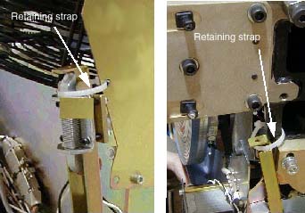
Figure 16. Cover Retaining Pins (Top and Bottom)
Press down firmly on the bracket and snap it into place. The locking mechanism on each upper bracket should lock the bracket securely into place. Do this on both sides. See Figure 17.
Figure 17. Locking the cover brackets into place.
- Remove lower cantrell brackets from service position (Figure 15), and rotate them into position over their associated retaining pins. Press down firmly on the bracket and snap it into place. See Figure 17.
- Remove upper Cantrell brackets from service position and rotate
them into position over their associated retaining pins. SeeFigure 15 and Figure 16.
- Remove dolly, disassemble and store safely away for later use.
- Reattach cables to cover.
- Re-install the Mylar (scan) window.
|
4 Finalization
Finalization
No finalization steps.