- Topic ID: id_18718264
- Version: 2.0
- Date: Feb 4, 2020 1:40:30 AM
GDAS(4/8) Detector Thermistor Replacement
Prerequisites
Procedure
- Verify that you have all the parts/tools required.
- Turn off 120VAC Gantry Power.
- Disconnect Detector Cable at J3.
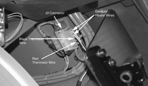
- Remove Thermistor wires/pins from J3 connector. These are the Red and
Black wires. Note their location within the connector. Use Pin extract tool.
Figure 1. J3 connector, showing thermistor wires
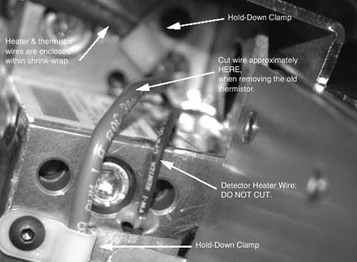
- Verify correct old Thermistor wires, then cut the old Thermistor cable
close to where the Thermistor cable and Detector Heater cables are joined
in the shrink-wrap sleeve. Do NOT cut the Detector Heater wires.
Figure 2. Approximate location for cutting thermistor wire
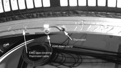
- Unscrew the Thermistor wire “Hold-down clamps”. There are two (2): one is near the end of the detector, the other is near the Thermistor.
- Carefully peel back the EMC tape covering the Thermistor wire so the
wire is free.
Figure 3. Remove old thermistor
- Unscrew and remove the Thermistor using a 9mm open-end wrench.
- notice
- Make sure the new Thermistor is clean before installing (No lint, dirt, debris, etc.)
- Screw in the new Thermistor until snug. Use finger pressure on wrench. Do not over-tighten. The metal Thermistor housing is only a shell. The wire should be free so it does not get twisted.
- Route the wire along the detector side just like the old wire, against the inner radius of the Heater element.
- Use EMC tape or Conductive tape to cover the wire.
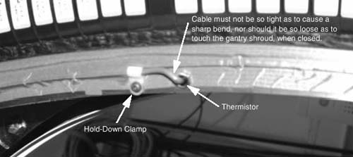
- Secure the wire with the 2 “Hold-down” wire clamps. Make
sure the wire is properly positioned at the Thermistor so it doesn't interfere
with the DAS Fan Air Plenum, and that the wire isn't too tight, creating a
sharp bend at the detector. It should also not be so loose as to get caught
or rub on anything during rotation.
Figure 4. Route new thermistor cable
- Route the wire along side the Shrink-wrapped cable going to J3. Ty-rap the new cable to the outside of the shrink-wrapped cable.
- Install the pins of the wire into the J3 connector.
- Connect J3 and confirm that any excess wire is secure and out of the way.
 |
Finalization
- Wait at least one (1) hour with power ON for the Detector to warm up.
- Verify detector temperature is 36 degrees Celsius
- Perform FastCal.
- Perform Image Quality Test Procedures. Take several scans for a couple of hours so that you are satisfied that the problem has been corrected.