- Topic ID: id_18718216
- Version: 2.0
- Date: Feb 4, 2020 1:40:22 AM
GDAS-4/8 Elastomers Replacement
Prerequisites
Overview
Procedure
- Position the table to its lowest position.
- Remove the gantry right side cover.
- Position the gantry at the 12 o'clock position.
- notice
- Turn OFF Axial Enable, HVDC, and 120VAC switches on the Service Switch panel.
- Remove the gantry top and front covers.
- Remove the DAS air plenum DAS Air Plenum Removal and Installation.
- Put on wrist strap and use good ESD precautions. Wear Finger Cots, and follow good Detector Handling practices.
- Remove appropriate Flex housing outer cover by removing the housing
Cover clamps.
-
A-side flexes must be removed to gain access to B-side flexes. To increase access space to the B-side, carefully bend the detached A-Side flex straight out towards the front of the gantry, so that it is perpendicular to the Detector window.
-
Each cover holds four (4) flex cables in place.
-
There are 2 clamps per cover. Each clamp is held by a 3mm captive hex cap screw. Use a 2.5mm Hex screwdriver bit to remove each clamp and cover.
-
Keep A-side and B-Side covers separate, as they are not interchangeable.
-
- notice
- Place an anti-static Detector Flex Boot on each exposed flex.
- Carefully remove the questionable elastomer from its seating.
- Insert the new elastomer so that the gold contact lines face outward.
Figure 1. “A-Side” Elastomer Installation
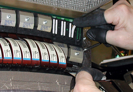
- Remove anti-static boots from flexes, and ensure that flex ends are clean. Clean with approved Alcohol pads, where required.
- Replace flex covers (B-Side first), and torque clamps to 13 in-lb (1.47 N-m).
- When complete, replace DAS air plenum.
- Remove rotational lock, restore power, and reassemble gantry covers.
 |
|
Finalization
No finalization steps.