- Topic ID: id_16157560
- Version: 3.0
- Date: Apr 9, 2020 8:49:02 PM
DAS-4/8 Chassis and Backplane Replacement
Prerequisites
Overview
The GDAS backplane is not a separate FRU; the entire chassis must be replaced. This procedure covers replacement of the left, center, and right chassis.
1 Chassis Removal (Left, Center or Right)
Procedure
 danger
- warning
- Position the table to its lowest position.
- Remove the gantry right side cover.
- Position the gantry at the 12 o'clock position.
- notice
- Turn OFF Axial Enable, HVDC, and 120VAC switches on the Service Switch panel.
- Remove the gantry top and front covers.
- Remove the DAS air plenum DAS Air Plenum Removal and Installation.
- Put on wrist strap and use good ESD precautions.
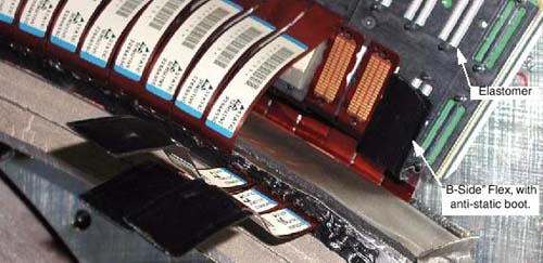
- Using Detector Handling precautions (verify use of ESD strap,
grounding and Finger Cots), disconnect Detector flexes from the appropriate
backplane (see Figure 1).
- Remove Flex housing outer (A-Side) covers by removing the housing
Cover clamps.
-
Left chassis: covers 11 - 15
-
Center chassis: covers 6 - 10
-
Right chassis: covers 1 - 5
There are 2 clamps per cover. Each clamp is held on by a 3mm captive hex cap screw. Use a 2.5mm Hex screwdriver bit to remove each clamp and cover.
-
- Carefully remove each flex from the backplane and bend each A-Side Flex straight out towards the front, so that it is perpendicular to the Detector window. This is to gain more access to the B-Side.
- Place an Anti-static Detector Flex Boot on each flex.
- Remove all Inner (B-Side) Clamps, covers, and flexes, using the same procedure as the A-Side. Place anti-static boots on flexes.
- Set the covers aside and keep them separated from the Inner (B-Side) covers. A-side covers are different from B-Side covers.
Figure 1. Flex Cables (With Anti-Static Boots)
- Remove Flex housing outer (A-Side) covers by removing the housing
Cover clamps.
- Disconnect the appropriate power cables:
-
Left chassis: J110, Power cable between Center and Left Chassis
-
Center chassis:
-
J99, Power cable between Center and Right Chassis.
-
J97, Power cable between Center and Left Chassis.
-
J72, Power Cable between Center Chassis and Power Supplies
-
J73, Power Sense Cable
-
-
Right chassis: J49, power cable between center and right chassis
-
- Disconnect the appropriate data cables:
-
Left chassis: J34, Data cable between Center and Left Chassis
-
Center chassis:
-
J8, Data cable between Center and Left Chassis.
-
J7, Data cable between Center and Right Chassis.
-
-
Right chassis:
-
J15, data cable between center and right chassis
-
J33, data cable between right chassis and DHCB
-
J31, CAN cable between right chassis and ORP
-
J32, data cable between right chassis and OBC
-
J30, CAN cable between right chassis and collimator
-
TX port, fiber optic cable between right chassis and slip-ring
-
note:Cover the appropriate DAS chassis with a towel or similar item to protect the DAS from particle contamination when removing or installing gantry balance weights.
-
- Remove weights as necessary for removal of chassis.

- notice
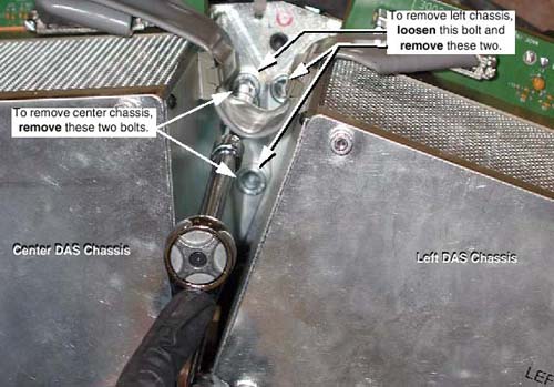
- While holding on to the DAS chassis, remove four (4) large 10mm
cap screws holding the chassis to the DAS mounting blocks (see Figure 2). When the last cap screw is removed, remove the chassis from the
Gantry and place on an ESD pad (to protect converter cards).
Figure 2. DAS Chassis Mounting Bolts (Between Left and Center Chassis)
-
The center chassis shares one bolt each with the left and right chassis.
-
When removing the left or right chassis, the second bolt on the shared side of the center chassis must be loosened slightly.
-
Be careful not to damage detector flexes.
-
|
2 Chassis Installation (Left, Center or Right)
|
|
Procedure
- Carefully place the DAS Chassis in position. Use special care:
-
Do not smash or otherwise damage Detector flexes
-
Keep Detector Flex Boots in place
-
Ensure that ALL Detector flexes are in front of backplane
-
- Secure by using four (4) large 12mm Cap screws, with Loctite
271 applied to each of the screw’s threads. Torque each chassis
mounting screw to 49 ft-lbs (66.4 N-m).
When replacing the left or right chassis, be sure to also tighten the center chassis bolt that was loosened for removal.
- Connect the appropriate power cables:
-
Left chassis: J110, Power cable between Center and Left Chassis
-
Center chassis:
-
J99, Power cable between Center and Right Chassis.
-
J97, Power cable between Center and Left Chassis.
-
J72, Power Cable between Center Chassis and Power Supplies
-
J73, Power Sense Cable
-
-
Right chassis: J49, power cable between center and right chassis
-
- Connect Data Cables
-
Left chassis: J34, Data cable between Center and Left Chassis
-
Center chassis:
-
J8, Data cable between Center and Left Chassis.
-
J7, Data cable between Center and Right Chassis.
-
-
Right chassis:
-
J15, data cable between center and right chassis
-
J33, data cable between right chassis and DHCB
-
J31, CAN cable between right chassis and ORP
-
J32, data cable between right chassis and OBC
-
J30, CAN cable between right chassis and collimator
-
TX port, fiber optic cable between right chassis and slip-ring
-
-
- If applicable, transfer the Converter boards from the replaced
chassis to the new chassis.
- Confirm ESD practices
- Remove Chassis board cover
- Remove 1 board at a time and transfer each board from the original chassis to the new chassis in the same board slot location.
- Install Detector flexes (B-Side)
- Confirm ESD and Detector flex handling practices. Use ESD Wrist strap and Finger Cots.
- Remove retainer that is covering housing and holding Elastomers in place.
- Verify all Elastomers are in their slots in the housings and are free from debris (spray with air).
- Remove Flex Boot and visually inspect each flex before installing for debris. Clean with approved Alcohol pads where required.
- Install Inner row (B-Side) flexes first.
- Install 4 flexes over appropriate housing slots and install cover and clamps to hold flexes in place. Torque each clamp cap screw to 13 in-lbs (1.47 N-m) no more, no less.
- B-Side Checkout
- Keep Axial switch Off, but turn on Gantry 120VAC and 550VDC switches.
- Do NOT Rotate Gantry because the A-Side Detector flexes are not connected.
- Turn on DAS Power switch
- Verify Converter board power-up diagnostics passed, via NO Board LEDs remain on.
- From the Operators console, perform a Hardware Reset
- Perform DAS / Detector Integration to verify B-Side connections
- When the B-Side is okay, install Outer row (A-Side) flexes.
- Install Detector flexes (A-Side)
- Turn OFF the DAS Power Switch and 550VDC Switch
- Remove Flex Boot and visually inspect each flex for debris before installing (spray with air). Clean with approved Alcohol pads where required.
- Install 4 flexes over appropriate housing slots and install cover and clamps to hold flexes in place. Torque each clamp cap screw to 13 in-lbs (1.47 N-m) no more, no less.
- Turn DAS and Gantry Power switches ON.
- Perform DAS / Detector Integration
- If applicable, install chassis board cover.
If the right chassis was replaced, reattach the fiber-optic cable to the transmit (TX) port.
- Install air plenum, per DAS Air Plenum Removal and Installation.
- Return weights to their original sequence and position (if applicable).
- Disengage rotational lock.
- Restore power.
- See “Finalization” for tests after replacing a DAS Chassis.
- Install / Close all covers.
3 Finalization
Procedure
- DAS Detector Integration
- Perform Interconnect and X-Ray Verification.
- Perform Pop Noise and Microphonics Test.
- Perform FastCal.
- PerformImage Quality Test Procedures .
- Perform a “Save System State”.