- Topic ID: id_18717841
- Version: 2.0
- Date: Feb 4, 2020 1:40:10 AM
DARC2 Scan Disk Replacement
Prerequisites
Overview
This procedure replaces the lower level FRU Scan Disks in the Westville or Jarrell DARC2. Both Scan Disks must be replaced in matching model number pairs.
1 Power Off (Shut Down) the Operator Console
Procedure
- Use one of the following methods to power off the Operator Console:
-
If Applications are running, click Shut Down on the desktop and select the Shutdown option.
-
If Applications are down, open a Unix Shell using the Toolchest and type: {ctuser@hostname} halt Enter.
The Operator Console monitor will display a “System Halted” message when it is acceptable to power off the Operator Console.
-
- Power OFF the Operator Console at the front panel switch.
- Make sure to follow all Lockout/Tagout requirements while performing this procedure. Refer to Equipment Service - Lockout -Tagout - PPE procedure. For added protection, disconnect the Twist-N-Lock Main Power Cable from the rear of the console.
2 Remove DARC2 Computer from Operator Console
Procedure
- Remove the front and rear Operator Console covers.
- Remove the cable connections to the DARC2 computer chassis. Verify each cable is clearly marked; if necessary, add a label for clarity.
- Remove and retain the front mounting screws, and then slide out the specific DARC2 computer.
- Put the DARC2 computer on a flat work surface.
3 Replace Scan Data Disk Drives
3.1 Disk Drive Removal on Jarrell and Westville DARC2
Procedure
- Remove the top cover from the DARC2 computer; retain the screws for reuse later.
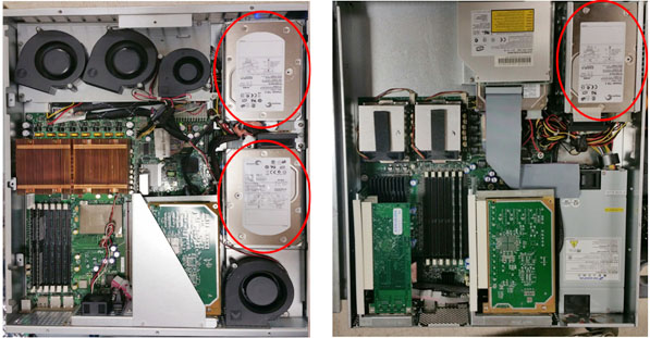
- Locate and remove the Scan Data Disk drives. See illustration
below.note:
For the Westville DARC2, the second disk drive is located below the top one.
Figure 1. DARC2 Disk Drive Locations – Jarrell (left); Westville (right)
- Remove the defective Scan disks. The replacement Scan disks
should be done in pairs and have matching model numbers.
- Remove the power cable and scsi cable.
- Remove the mounting brackets and drive from the DARC2.
- Remove the mounting bracket from the disk drive (the bracket will be reused).
3.2 Disk Drive Replacement on Jarrell & Westville DARC2
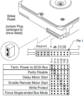
The jumper settings in this section are for the Seagate ST373455LW.
Procedure
- Remove all jumpers in J6 as shown below.
Figure 2. Disk Drive J6 Jumper Setting
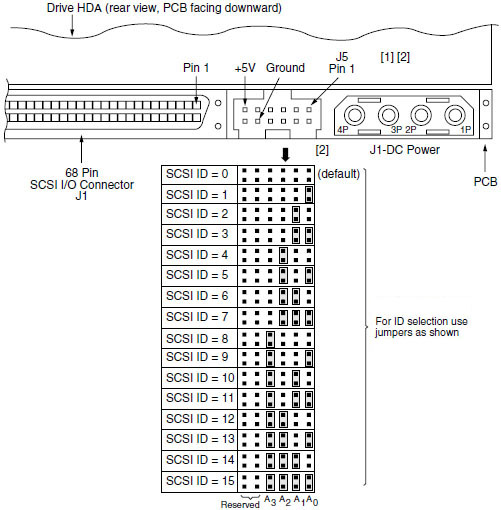
- Jumper setting on J5 Figure 3: There are two disk drives; one is ID 0, the
other is ID 1. Ensure one disk drive is set as SCSI ID = 0 and the
other is set as SCSI ID = 1.
Figure 3. Disk Drive J5 Jumper Setting
- Install the replacement disk drives into the previously removed mounting brackets.
- Install the disk drive bracket assembly into the DARC2.
- Reconnect the cables to each replacement disk drive.
- Replace the top cover and install the mounting screws.
4 Reinstall DARC2 Computer in Operator Console
Procedure
- Slide the DARC2 computer into the Operator Console from the front.
- Secure the DARC2 computer chassis to the Operator Console using the mounting screws retained earlier in the procedure.
- Reconnect the cables to the DARC2 computer.
- Verify the power switch is set to the ON position (the Westville switch is located at the rear of the DARC2).
5 Power-On the Operator Console
Procedure
- Reconnect the Twist-N-Lock Main Power Cable from the rear of console and remove the Lockout/Tagout protection applied earlier. Power ON the Operator Console at the console’s front panel switch.
- Stop applications from coming up.
- Recreate the GRE-RAID disk array:
- Open a Unix shell as ctuser.
- Type: rsh DARC Enter.
- Type: sudo gre-raid -z –c Enter.note:
For PET systems running pet_libhp1.39 do NOT run the sudo gre -raid -c command. The reconfig command in the step below will run the reconfigScanDisk process.
- At the prompt “Are you sure you want to create a new disk array (yes/no)” type: yes Enter.
- Verify gre-raid success message is displayed.
- Type: exit Enter.
- Regenerate the database:
- Open a Unix shell.
- Type: su – Enter.
- Enter the root password.
- Type: reconfig Enter and select Config.
- Select regenerate database and confirm by selecting Yes.
- Select Accept and confirm reboot now by selecting Yes.
- Wait until the reboot completes and then restore full Insite
functionality:
- Open a Unix shell.
- Type: su – Enter.
- Type: cd /usr/g/insite Enter.
- Type: ConfigLink Enter.note:
ConfigLink is only present if an Insite checkout was previously done. If Insite checkout was not previously done you may see a “command not found” response that can be ignored.
- Remove files from the recovery directory:
- Type: cd /usr/g/data_management/recovery Enter.
- Type: rm -f 1* Enter.
note:There may be no files to remove so a response of no files found can be ignored.
- Restart applications:
- Open a new Unix shell as ctuser.
- Type: st Enter.
6 Finalization
Procedure
- Run a test scan and verify that the image(s) reconstruct and successfully display.
- Reinstall the Console Front and Rear Covers.
- Verify the SCSI drive has Firmware revision 1 (Fwrev = 0001)
by using the lsscsi command (only rev 1 has been validated):
- Open a Unix shell as ctuser.
- Type: rsh darc Enter.
- Type: lsscsi Enter.
Example lsscsi output (correct Fwrev):
Device-Bus-ID Media Mfg Model Fwrev Device
[0:0:0:0] disk SEAGATE ST373455LW 0001 /dev/sda
[0:0:1:0] disk SEAGATE ST373455LW 0001 /dev/sdb
- Close the Unix shell.
Finalization
Perform the following after applications software is back up.