- Topic ID: id_18718498
- Version: 1.0
- Date: Sep 20, 2018 2:05:50 PM
Console Bulkhead Replacement
Prerequisites
Overview
This module describes the procedures used to upgrade the Console Bulkhead. The new bulkhead has three additional RJ45 ports, to allow the direct connection of the ECG device, the Injector Device, and an Auxiliary Printer.
1 Power-Off (Shut Down) the Console
Procedure
- Select one of the following methods to Power OFF the Operator Console:
- If Applications are up, click on the [Shut Down] button and select [Shutdown]. The Operator Console monitor will display a 'Power Down' message when it is acceptable to power OFF the Operator Console.
- If Applications are down, open a Unix Shell. Type: halt. The Operator Console monitor will display a 'Power Down' message when it is acceptable to power OFF the Operator Console.
- Power OFF the console at the front panel switch.
2 Remove the Old Bulkhead
Procedure
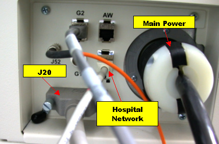
- The old bulkhead is shown in Figure 1.
Figure 1. Old Bulkhead Assembly
- Remove the front and rear Operator Console covers.
- Unplug the main Power from the Console Bulkhead.
- Unplug the Hospital Network Cable from the Console Bulkhead and label if not already labeled.
- Remove the 4 screws holding the bulkhead in place and retain for later use.
- Pull the Bulkhead slightly.
- Disconnect the J20 Cable from the Bulkhead, and label appropriately if it is not already labeled.
- Unplug J52, Data Cable.
- Unplug any other Network Connections that may be plugged in.
- Disconnect G1, from both sides of the bulkhead.
- Disconnect fiber optics cable from both sides of the bulkhead.
- From the Host Computer disconnect:
- G2 Ethernet Cable – HOST “Ethernet Port D”
- Network Host “Ethernet Port A”
- AW – Host Network
- Remove the old bulkhead and set it aside.note:
Refer to the schematic located on the rear console cover for cable connection details.
3 Install Ethernet Switch
Procedure
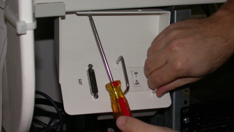
- Remove the power switch assembly, using a 3mm Allen Wrench or Phillips
Head screw driver depending on your console configuration.
Figure 2. Remove the Power Switch Assembly
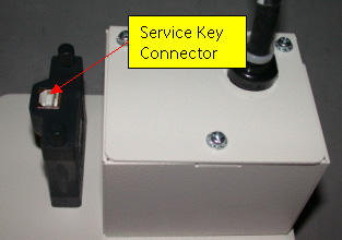
- Remove the Service key cable from the power switch assembly.
Figure 3. Service Key Connector
- Remove 3 screws from the power switch assembly and pull cover plate away from the assembly.
- Disconnect the power cable from their connection terminals.
- Move the power switch from the old power switch assembly to the new one.
- Connect the new power switch assembly to the power cable.
Figure 4. Power Switch Assembly
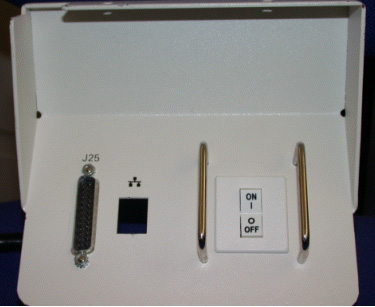
- Move J25 connector from the old power switch assembly to the new one and set aside.
4 Install Mounting Bracket
NOTE: Skip this section for GOC4 Upgrades.
Procedure
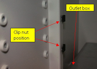
- Attach 2 mounting clip nuts to the pre-drilled holes just above the
outlet box. Take caution not to drop the mounting screws or clip nuts behind
the power box.
Figure 5. Clip Nut Position
- Attach L Mounting Bracket to the vertical rails using existing 4mm threaded
holes. Loosen the existing screw (see Figure 6) and add one of the three 4mmx3mm phillips head screws
to the front; tighten only half way.
Figure 6. “L” Mounting Bracket
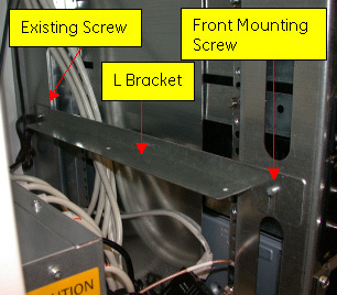
- Slide the L Bracket onto the two loose screws and tighten.
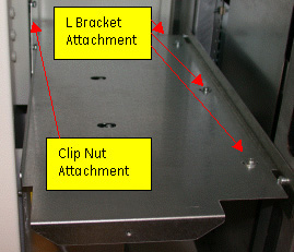
- Attach the Upper support bracket using qty 2- 4mm x 16mm allen wrench
screws to the clips installed in step 1 and qty 3-phillips head 4mmx8mm screws
to the L bracket.
Figure 7. Upper Support Bracket
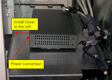
- Velcro the ethernet switch on top of the bracket insuring that the ports
are facing the right side of the chassis.note:
Mount the ethernet switch centered more to the left of the upper support bracket. Plugging in the power to the switch is also recommended before securing the switch to the Velcro.
Figure 8. Ethernet Switch Placement
5 GOC4 Ethernet Switch Mounting.
Mount Ethernet switch on top of the ICOM using the Velcro.
6 Install the New Bulkhead
Procedure
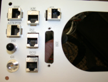
- The new bulkhead is shown in Figure 9.
Figure 9. New Bulkhead
- Reinstall the J20 Cable to the bulkhead.
- Route the ethernet bundle through the right side of the bracket.
Figure 10. Route Ethernet Bundle
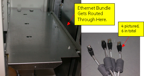
- Plug each cable into the Ethernet switch. Each cable is labeled with
the port it should be connected to.
- INJ (Injector) cable connects to Ethernet Switch 2.
- ECG cable connects to Ethernet Switch Port 3.
- AW cable connects to Ethernet Switch Port 4.
- AUX/PTR cable connects to Ethernet Switch 5.
- HOST cable connects to Ethernet Switch Port 8.
- Route the remaining cables to the back of the console chassis and connect
to their appropriate places.
- The G2 cable connects to the Host Port D.
- Connect the Host Ethernet Cable (the other end goes to Ethernet Switch Port 8)
- Hospital Network Connector goes to HOST Port A.
- Connect J52 and Fiber cable to back of the new bulkhead.
- Reconnect the new rear bulkhead reusing the four screws removed from
the old bulkhead.
From inside the chassis, gently pull on the cables to loosen some of the tension.
- Attach the new front panel switch.
- Connect the Service panel cable to Ethernet Switch port
- Connect the Service Key cable
- Connect the switch panel to the console.
- Mount new power switch assembly using a 3mm Allen Wrench or Phillips Head screwdriver, depending on your console configuration.
7 Finalization
Procedure
- Replace Covers.
- notice
- Reconnect the Hospital Network cable.
- Reconnect the Console main Power.
- Power on and Test the system.
 |