- Topic ID: id_16158054
- Version: 3.0
- Date: Jun 10, 2020 2:24:25 AM
CBF/SAG Alignment Process
Prerequisites
Overview
CBF/SAG Alignment ensures the focal spot is accurate, the bowtie filter is centered and center of rotation is in a straight line.
Figure 1. CBF Procedural Flow
note: For a larger version of the above illustration, click on the link to open pdf file: CBF Procedural Flow.
note: When performing alignments, wait at least 15-30 minutes between scans to prevent unnecessary adjustments.
1 Accessing the Software
Procedure
- Select SERVICE DESKTOP.
- Select Calibration.
- Select CBF and SAG Alignment to enter
‘CBF feature” UI.
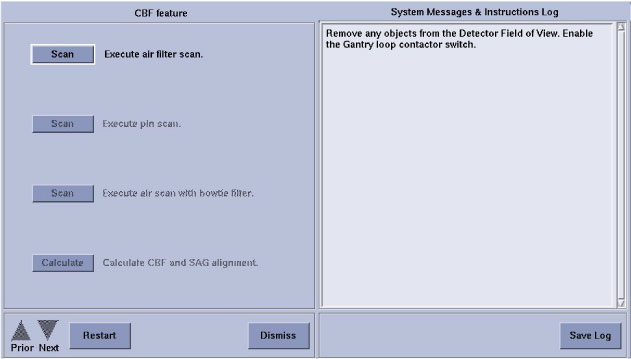
Figure 2. CBF/SAG Alignment Program Screen
2 Adjustment Procedure
Procedure
- Click on the Scan button to Execute air filter scan.
- Place the 1/8 inch screw driver on the phantom holder (should be pointing into the Z direction).
- Execute pin scan.
- Execute air scan with bow-tie filter.
- Click on the Calculate button to Calculate CBF and SAG alignment.
- Mount indicator onto the lower dial mounting bracket (Figure 3). Make sure that you zero the Dial Indicator.
- Rotate the Gantry to place the tube at the 3 o’clock position.
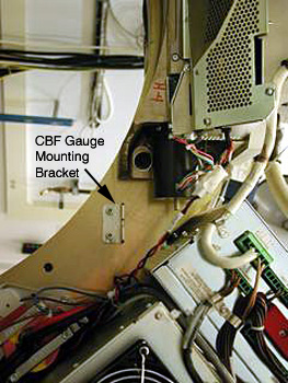
Figure 3. CBF Dial Indicator
- Loosen the six (6) M14 collimator cap screws. Four (4) cap screws
are on the front side of the collimator. (One cap screw is behind
the cable connections. Use a swivel adapter for ratchet wrench.) Two
(2) cap are screws on the rear (through the rotating base casting).
See Figure 4.note:
Be careful not to move the laser light. If you do, you will need to re-align the lights.
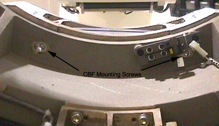
Figure 4. Collimator CBF Rear Mounting Screws
- Adjust the Collimator as indicated by the results of the calculation. (Ignore the negative sign in front of the adjustments.)
- Tighten the Collimator.
- Re-scan and calculate.
- Proceed to the next step if the adjustment is within limit, otherwise jump to step 8.
- Torque all six (6) M14 cap screws to standard torque value.
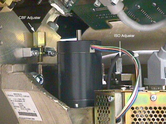
Figure 5. CBF Adjuster Location
3 Finalization
No finalization steps.