- Topic ID: id_16158034
- Version: 3.0
- Date: Nov 27, 2020 2:07:03 AM
Alignment Light Adjustment
Prerequisites
Overview
Procedure
- Remove gantry covers as required.
Refer to
- Remove cradle pad and associated accessories.
- Place Large Phantom on end of cradle so it extends 2 inches beyond the cradle end.
- Verify phantom is level front to back and side to side.
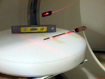
- Assemble washer and screwdriver and secure to phantom as shown in Figure 1.
Figure 1. Internal and External Laser Alignment Jig Setup
 danger
- Turn on laser lights using gantry control panel.
- Adjust jig position such that:
-
Internal lasers shine on the washer’s edge center
-
Sagittal and Coronal lasers shine on the center of the screwdriver shaft
note: Chose either the left or right side of the jig as a reference for this procedure. -
- Select New Patient, Baby, 20.1 Service Generic Scan, Create New Series,
Scout.
- Confirm and Scan.
- Image Works, Browser Select Exam, Series, Image.
- Select Format one over one (lower left)note: Both scout should now be displayed. Adjust the window and level setting so you can see the outline of the screwdriver handle. Click in a viewport to activate it, and select Grid.
The washer and screwdriver shaft need to be centered under the zero (0) grid lines. Both washer and screwdriver should also be parallel to the associated grid lines. See Figure 2.
Figure 2. Aligning the Laser Adjustment Jig to ISO Center and the Z-Axis
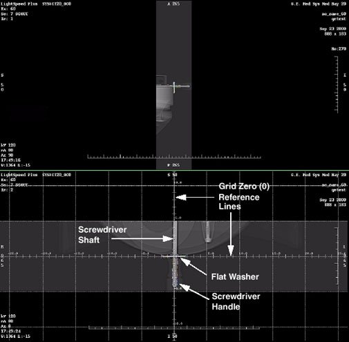
- Write down the error delta from the Zero (0) grid lines to the center of the screwdriver shaft and washer edge. Use measure distance if desired.
- Position the jig exactly the error delta using gantry controls. DO NOT
MOVE THE PHANTOM.note: Changing Elevation will post an error window. Ignore this and proceed.
- Select Repeat Series and scan.
- Repeat Step 8 through Step 14 until jig reference points are centered under the grid zero (0) lines.
- notice
- Press the Internal Landmark button to zero the cradle position display.
- danger
- Press the Alignment Lights button.
- danger
- Turn OFF Axial Enable switch.
- Adjust the Reference Internal Laser chosen in step 7 to shine on the
washer’s edge center. Reference Figure 3.
Mounting Screws Angular Alignment Screw Position Alignment Screws
Figure 3. Laser Adjustment Screws
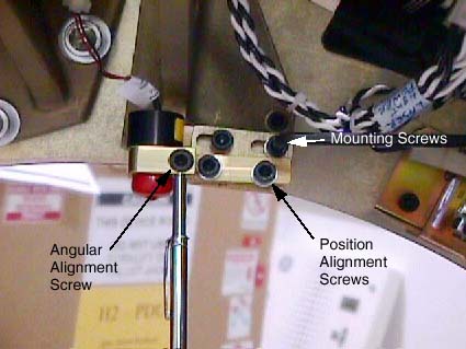 note: Properly adjusted Lasers will bisect the output port of the other 2 Internal lasers.
 - Adjust the Sagittal and Coronal lasers so they shine on the screwdriver shaft at ISO Center. Set Coronal lasers as level as possible and Sagittal laser as parallel to the cradle as possible. Tracking adjustments will be performed in later steps.
- Move the cradle out of the gantry to 240 mm position, using the gantry control panel.
- Adjust the Reference External Laser to shine on the washer’s edge
center.note: Properly adjusted Lasers will bisect the output port of the other External laser.
- After Reference Lasers have been adjusted, raise and lower the table, and verify both the External and Internal lasers track the washer’s edge center.
- notice
- Repeat Step 19 through Step 23 as needed.
- Remove the screwdriver jig without disturbing the phantom.
- Now that the reference lasers have been set, use a piece of notebook paper to adjust the other Internal and External lasers to coincide with the reference lasers Alignment Lights Visual Checks.
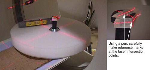
- Place another object, such as a full contrast bottle or unopened soda can, on the phantom. Attach masking tape and position the object at ISO Center using the laser lights. Refer to Figure 4.
- Using a pen, carefully mark the laser intersection points on the masking
tape. Once set, DO NOT DISTURB THE JIG.
Figure 4. Sagittal and Coronal Laser Alignment Jig Setup
- Using the gantry control panel, move the cradle out of the gantry to 240 mm. Verify the Sagittal and Coronal laser lights track your pen marks.
- notice
- The last adjustment is the un-referenced Coronal laser to the Reference Coronal laser chosen in Step 7 (See Alignment Lights Visual Checks).
- Assemble the gantry.
 |
|
|
Finalization
- Perform Alignment Lights Visual Checks.