- Topic ID: id_15460177
- Version: 4.0
- Date: Sep 26, 2020 10:13:39 PM
2010 Axial Drive Power Supply Replacement
Prerequisites
Overview
Demonstrates how to install a new axial drive power supply into the 2010 axial drive assembly.
1 Preparation for Replacement
Procedure
- notice
- Stop the rotor of X-ray tube in case of Liquid Bearing Tube before HVDC off. Refer to Liquid Bearing Tube Rotor stop procedure for details.
- Remove gantry right side cover and disable Axial Drive, HVDC and 120VAC service switches from the Service Switch Panel. Refer to Replacement > Gantry > Enclosure > Cover Removal Procedures for removal and replacement of covers.
- Remove the gantry left side, top and front covers. Connect the cover E-stop circuit to the terminators on the gantry.
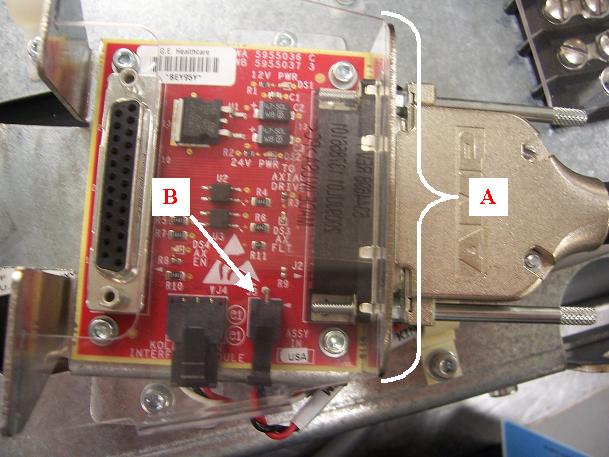
- Remove the plastic shield and disconnect red and black cable
from the smaller port on the KIM board assembly (refer to Figure 1).
Figure 1. Cable connection from power supply to KIM board
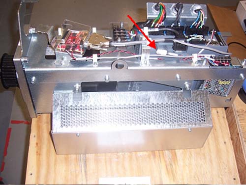
- Disconnect power supply (blue and brown) wire from 2010 axial
drive (refer to Figure 2).
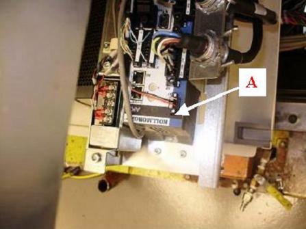
Figure 2. Holding brake wire connection point
- Pull the cables out of the cable clamps for the cables running to the power supply. These are supplied with the new part.
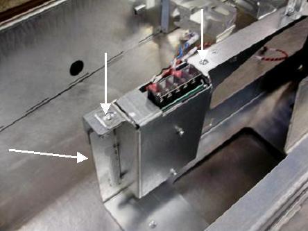
- Remove the three screws mounting the power supply assembly to
the axial drive assembly. The bottom mounting screw is accessible
from the outside of the axial drive assembly. See Figure 3.
Figure 3. Mounting of Power Supply to Axial Drive
- To remove the power supply, pull supply assembly up and out of the top of the chassis.
 |
2 Installation of new Power Supply Assembly
Procedure
- Mount power supply assembly onto axial drive assembly with three
M6 screws, lock washers and flat washers using a 5mm hex wrench. Refer
to Figure 3and table below.
- Connect red and black cable from the power supply into the KIM
board port and reinstall plastic shield over KIM board. See Figure 1. Guide cable
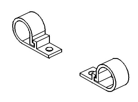
through the two plastic cable clamps on the route between the power
supply and KIM board. See Figure 4 for visual reference of plastic cable clamps.
Figure 4. Plastic Cable Clamps
- Connect other cable to the power supply wire (blue and brown) from the 2010 axial drive. See Figure 2. Guide wire through plastic cable clamp near the power supply (see Figure 4).
3 Reassembly of Gantry
Procedure
- Turn on the 120VAC switch from the Service
Switch Panel. An 'o2' code should show up on the display of the axial
drive controller (refer to Figure 5)
Figure 5. “o2” code display
- Turn off 120VAC switch from the Service Switch Panel.
- Install the gantry front cover, then the top and left side covers.
- Turn on the 120VAC, Axial Drive, and HVDC service switches from the Service Switch Panel.
- Install the gantry right side cover.
4 Finalization
Procedure
- Run System Scanning Test from the Functional Checks procedure list.