- Topic ID: id_11038854
- Version: 4.0
- Date: Mar 4, 2022 1:21:17 AM
Collimator Functional Diagnostic Tests
1 Overview
This module explains how to run the “Collimator Functional” tests, which exercise the cams and filter motions and encoder responses.
2 Preparation
(For Liquid Bearing Tube ONLY)
- Open command window and execute "rotor_ctrl -start" command before the procedure execution. Refer to Rotor Control Tool with LB Tube - Command manual for details.
3 Procedure
- Select the DIAGNOSTICS or DIAGNOSTICS – X-Ray Generation tab in the common service desktop.
- Launch the COLLIMATOR FUNCTIONAL.
- Collimator Application Position Test
Figure 1. Collimator Application Test GUI
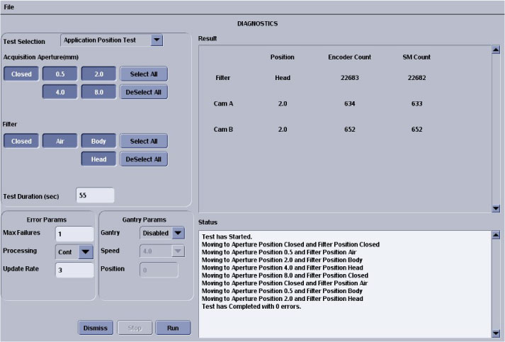
- Diagnostic Description
This test continuously positions the collimator and filter to the selected position.
- When (to use)
-
Test runs in continuous modes, which help detect intermittent operating conditions.
-
Means to visually validate the aperture and filter positions.
-
Functional validation of the operation of the collimator.
-
- What (to look for)
Look for highlighted fields that indicate the cam or filter did not make it to position. Check the log for additional information, when this occurs.
- Notes
-
Test can be run from application or diagnostic firmware download.
-
Watch for finger pinch hazards.
-
Attempt to move the filter and/or cams, when test is complete, and verify motor has a lot of holding torque.
-
- Diagnostic Description
- Collimator Continuous Filter Position Test
Figure 2. Collimator Continuous Filter Position Test GUI
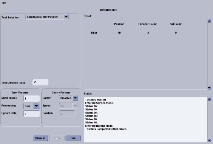
- Diagnostic Description
This test continuously moves the filter from one extreme to another.
- When (to use)
-
Verify no mechanical binding is present.
-
Manual mode for signal tracing.
-
Check for motion when errors indicate no motion sensed.
-
- What (to look for)
If the display does not indicate changes in the encoder count, visually check the filter for motion:
-
If filter is moving, failure is in the encode circuit.
-
If filter is not moving, failure is in the drive circuit.
-
- Notes
-
Test can be run in the applications and diagnostic download.
-
Watch for finger pinch hazards.
-
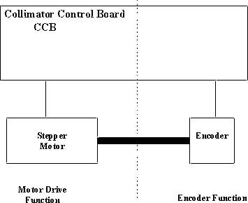
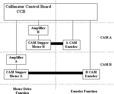
The filter drive can be divided into two functions:
-
Motor Drive (Positioning driver).
-
Encoder (Position feedback).
-
Figure 3. Collimator Filter Position
-
- Diagnostic Description
- Collimator Continuous CAM Rotation Test
Figure 4. Collimator Continuous CAM Rotation Test
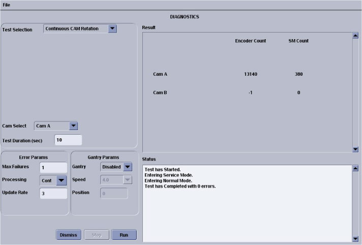
- Diagnostic Description
This test continuously rotates the selected CAM.
- When (to use)
-
Verify no mechanical binding is present.
-
Manual mode for signal tracing.
-
- What (to look for)
-
If the display does not indicate changes in the encoder count, visually check the cam for motion.
-
Listen for mechanical vibration or binding.
Figure 5. Collimator CAM Rotation
-
- Notes
-
Test can be run in the applications and diagnostic download.
-
Watch for finger pinch hazards.
-
CAM A and B circuitry is the same.
-
CAM operation can be divided into four functions:
-
- Diagnostic Description
- Collimator Encoder Test
Figure 6. Collimator Encoder Test Screen
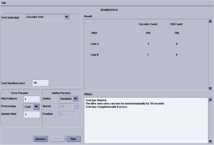
- Diagnostic Description
Reads and displays the CAM and filter encoders while the devices are manually positioned.
- When (to use)
Confirm an encoder problem with the collimator.
- What (to look for)
Verify encoder reading changes once the cams or filters are moved. See below for relative encoder counts.
- Notes
-
Test can be run in the applications and diagnostic download.
-
Watch for finger pinch hazards.
-
Test reduces the cam holding torque to allow the cams to be rotated by hand.
-
Cams are 2000 counts per rotation.
-
Filter is 1000 counts per rotation.
-
Cam encoder requires the whole collimator to be replaced.
-
Filter housing assembly is a FRU.
-
- Diagnostic Description
- Collimator Application Position Test
4 Finalization
No finalization steps.