PC BIOS Install & Setup for HP xw8000 Host Computer
1 Introduction
(For GOC3, GOC4, and GOC5 Operator Console systems) This procedure describes how to verify and/or flash the HP xw8000
BIOS (JQ.W1.13US version) with default HP BIOS settings and then set
up the BIOS to specified GE settings. If unsure about the state of
current settings, set the defaults first using the main BIOS menu
option.
The floppy disk for flashing is labeled: CT HiSpeed
/ LightSpeed Linux Console BIOS v1.13 (PN 5138295)
note:
If you know that the BIOS software is at version 1.13
but suspect that the Host BIOS settings may be incorrect, proceed
to Enter BIOS Menu for step-by-step instructions to verify the GE-specified
settings, or if you don't need step-by-step instructions, you can
simply refer to the tables in Appendix A: Reference Charts for Specified GE Settings.
Refer to Appendix A for Purchase Specification information.
2 Flash the Host BIOS via Floppy
If the application software is up, use the following
command in a Unix Shell to bring Applications software down:
{ctuser@hostname} cleanMon
Open the Operator Console front cover.
Insert the proper floppy disk CT HiSpeed
/ LightSpeed Linux Console BIOS v1.13 into the Host Computer.
When Application Software is down, at the toolchest
open a Unix Shell and type:
{ctuser@darc}halt
The Operator Console monitor will display a System halted message
when it is acceptable to power OFF the Operator Console.
note:
(For 06MW03.X Software) Wait 1-2 minutes
after the “System halted” message appears to allow the
VDARC Node to properly power-down. SW release 06MW29.7 and later has
corrected this issue.
Power OFF the Operator Console at the front panel
switch.
Wait 30 seconds to allow all disk drives to settle;
then power ON the Operator Console at the front panel switch.
Power ON the Operator Console at the front panel switch.
As the Host Computer restarts, the floppy disk boot
process message will appear.
When the BIOS Setup Utility screen
is displayed, select A Flash BIOS by typing A and pressing the Enter key.
The BIOS will begin to flash from the floppy. Allow the BIOS
to flash completely.
When a message including “PRESS ANY
KEY TO RESTART THE SYSTEM” is displayed, first remove
the BIOS floppy disk from the drive. This prevents a second boot-up
from floppy.
Next, press any key on the keyboard, for example, Spacebar. The Host Computer will proceed to reboot.
Tthe BIOS flash process is now complete.
3 Enter BIOS Menu
If you did not flash the Host BIOS via floppy, reboot
the Host Computer now.
When the hp invent screen appears
on the monitor, press F2 to interrupt the boot-up
sequence and to enter the Host BIOS setup mode.
Verify that the Main screen is
displayed.
View the BIOS Version and verify
it is JQ.W1.13US.
4 Set Up the Host BIOS
4.1 Host BIOS “Main” Settings
Changes can be made by cursor-selecting the parameter, then
using the + and - keys on
the numeric keypad to toggle its value.
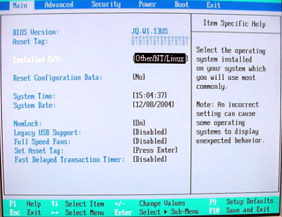
The Main setup screen is shown in Figure 1. Confirm that the following parameters are set as follows:
Installed O/S: [Other/NT/Linux]
Legacy USB Support: [Disabled]
Figure 1. Main Setup Screen
4.2 Host BIOS “Advanced” Settings
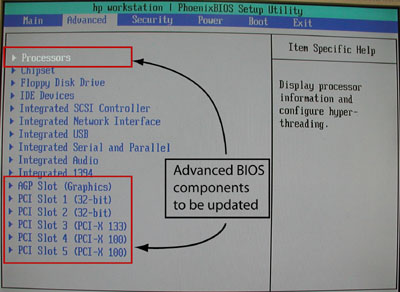
From the Main screen, use the right arrow to navigate to Advanced. The Advanced setup screen is shown below.
The BIOS components that will be updated in the next steps are detailed
in Figure 2.
Figure 2. “Advanced” Settings Screen
Use the down arrow to navigate
to Processors and press Enter.
Set the following Processors parameter
as indicated:
Hyper-Threading [Enabled]
Press Esc to return to the Advanced screen.
Navigate to AGP Slot (Graphics) and press Enter.
Set the following AGP Slot (Graphics) parameters as indicated:
Enable Master: [Enabled]
(For PET RW 2368697-7) (For all others) Graphics Aperture: [64MB] or [128Mb]
Press Esc to return to the Advanced screen.
Navigate to PCI Slot 1 and press Enter.
Set the following PCI Slot 1 parameter
as indicated:
Option ROM Scan:[Disabled]
Press Esc to return to the Advanced screen.
Navigate to PCI Slot 2 and press Enter.
Set the following PCI Slot 2 parameter
as indicated:
Option ROM Scan:[Disabled]
Press Esc to return to the Advanced screen.
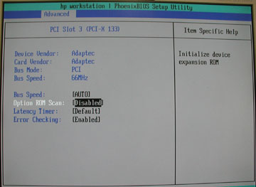
Navigate to PCI Slot 3 and press Enter.
(For Adaptec)
Set all PCI Slot 3 parameters as shown
in Figure 3.
(Specifically, set Option ROM Scan to [Disabled].)
Figure 3. Advanced PCI Slot 3 Screen
(For QLogic) (Device Vendor and Card Vendor are listed as 1077H.)
Set all PCI Slot 3 parameters as shown
above, EXCEPT
Set Option ROM Scan to [Enabled].
Press Esc to return to the Advanced screen.
Navigate to PCI Slot 4 and press Enter.
Set the following PCI Slot 4 parameter
as indicated:
Option ROM Scan:[Disabled]
Press Esc to return to the Advanced screen.
Navigate to PCI Slot 5 and press Enter.
Set the following PCI Slot 5 parameter
as indicated:
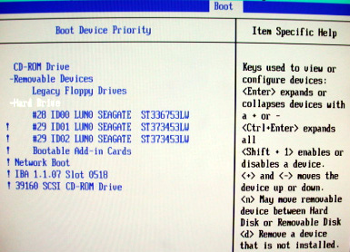
Set the sequence of drives in the following order:
Legacy Floppy Drives
CD-ROM Drive
Hard Drive
To do this, navigate to each item to be moved and
then use either the + or - key to move the item to the correct sequence.
Arrow-select (move to) Hard Drive and press Enter again.
Set the hard drive parameters as shown in Figure 5.
note:
The ! indicates that the device is
disabled.
Select each parameter and press the Shift and 1 together to enable or disable it. This
is indicated by ! shown for each parameter disabled
but not shown for enabled.
This means ID00 LUN0 should be the only
hard drive enabled (without !).
Figure 5. Boot Device Priority Screen
Press Esc to return to the Boot screen.
4.5 BIOS Completion
Save the BIOS settings:
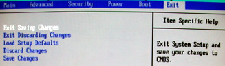
Navigate to the Exit tab.
Select Exit Saving Changes and
press Enter. See Figure 6.
Figure 6. “Exit” Screen with Save
Select [Yes] and press Enter again to “Save configuration changes
and exit now”. See Figure 7.
Figure 7. Save Configuration Screen
At this point, the Host BIOS setup is complete.
note:
After saving the configuration changes and rebooting,
the SCSI CD-ROM drive shown as the last item listed inFigure 5 may be missing,
as indicated by the message:
Adapter/configuration may have changed, reconfiguration
is suggested! Press Ctrl-C to start LSI Logic Configuration Utility…
Ignore this message.
5 LSI Logic MPT SCSI Setup
5.1 Initialization
The following steps verify that the SCSI channel settings are
set correctly for each channel/disk/controller. The SCSI Setup is
set back to default values when the BIOS is flashed. If an issue occurs,
reflash the Host BIOS then perform the Section 4 “Set Up the
Host BIOS.”
Remove power to the host computer by pressing the
power button on the front for 5 seconds.
Reboot the Host Computer by pressing the power button
again.
While the computer is booting, verify at the bottom-left
of the screen that the BIOS version indicates 1.13. Press any key.
When prompted, press Ctrl + C to interrupt the boot-up sequence and to start the LSI
Logic SCSI Configuration Utility.
5.2 “SCSI Channel 0” Settings
Overview: The following steps verify that the SCSI channel settings
are set correctly for each channel/disk/controller.
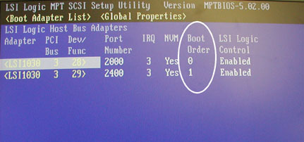
In the LSI Logic MPT SCSI Setup Utility, select the adapter which is identified by “Boot Order 0”
and press Enter to access the Adapter
Properties menu.
Figure 8. Boot Adapter List - Boot Order 0
The process shows: Scanning for devices
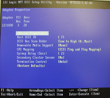
Figure 9. Adapter Properties Window
Verify that the settings are as shown above.
Highlight Device Properties and
press Enter.
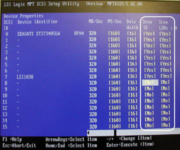
For SCSI ID 0 through SCSI ID 7, verify that Scan ID and Scan LUN values are set to [Yes] as
shown below.
If needed, navigate to any that need to be changed and press
the - key to toggle the Scan ID and Scan LUN values to [Yes].
Figure 10. Device Properties for OS Drive - Scan ID and Scan LUN
For SCSI ID 8 through SCSI ID 15, set Scan ID and Scan LUN to [No] as shown above.
Navigate to those that need to be changed and press the - key to toggle the Scan ID and Scan LUN values to [No].
Press Esc to exit the Device Properties setup screen.
Press Esc to exit the Adapter Properties screen.
(For when changes were made) Navigate
to (Save Changes then exit this menu), and press
the Enter to save the changes.
5.3 “SCSI Channel 1” Settings
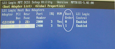
In the LSI Logic MPT SCSI Setup Utility, select the adapter which is identified by “Boot Order 1”
and press Enter to access the Adapter
Properties menu.
Figure 11. Boot Adapter List - Boot Order 1
The process shows: Scanning for devices
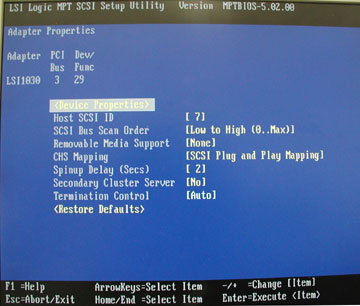
Figure 12. Adapter Properties - Boot Order 1
Verify that the settings are as shown above.
Highlight Device Properties and
press Enter.
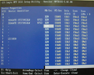
For SCSI ID 0 through SCSI ID 7, verify that Scan ID and Scan LUN values are set to [Yes] as
shown in Figure 13.
If needed, navigate to any that need to be changed and press
the - key to toggle the Scan ID and Scan LUN values to [Yes].
Figure 13. Device Properties for Image Disk 1 and Image Disk 2 - Scan
ID and Scan LUN
For SCSI ID 8 through SCSI ID 15, set Scan ID and Scan LUN to [No] as shown in Figure 13.
Navigate to those that need to be changed and press the - key to toggle the Scan ID and Scan LUN values to [No].
Press Esc to exit the Device Properties setup screen.
Press Esc to exit the Adapter Properties screen.
(For when changes were made) Navigate
to (Save Changes then exit this menu) and press Enter to save the changes.
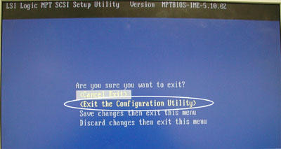
Press Esc to exit the LSI Logic MPT SCSI Setup Utility screen.
Select (Exit the Configuration Utility) and press Enter.
Figure 14. Exit the Configuration Utility
6 Appendix A: Reference Charts for Specified GE Settings