- Topic ID: id_18717915
- Version: 1.0
- Date: Sep 20, 2018 2:03:48 PM
Manually Configuring System INFO
This procedures describes the steps necessary to manually configure system INFO.
-
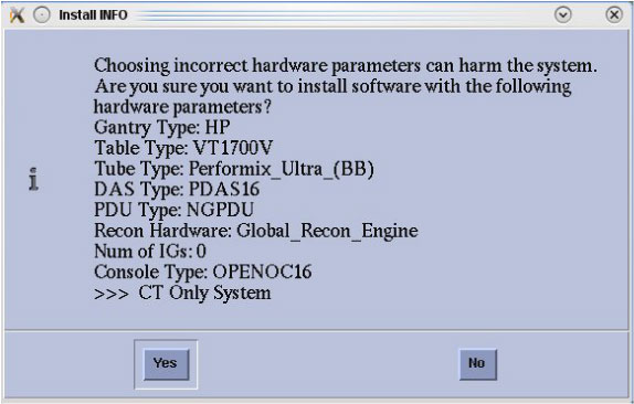
When the system state Install INFO decision box appears, click No.
Figure 1. Install INFO Decision Box
-
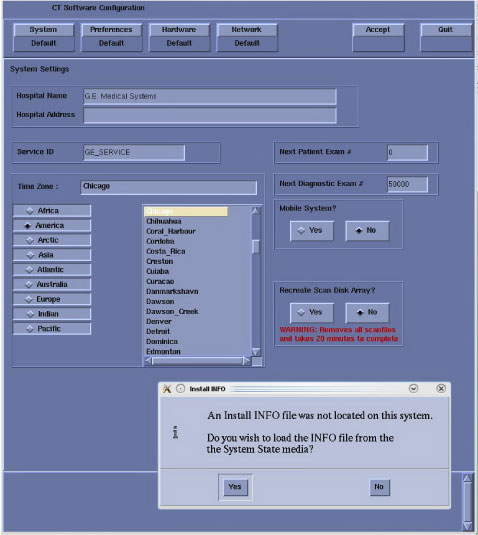
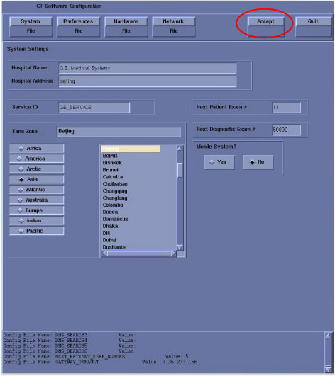
Select: System to access System Settings screen.
Figure 2. System Setting Screen
-
Verify that the Next Patient Exam # on the System Settings screen is the value restored from Save System State. Otherwise, set to 1.
-
Verify that the proper Time Zone is selected.
Select/enter information as required for your system configuration.
-
-
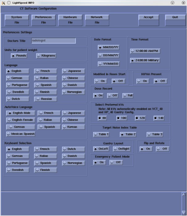
Select: Preferences to access Preferences Settings screen.
Figure 3. Preferences Settings Screen
-
Select the units for patient weight.
-
Select Language: (English or other).
note:To select additional 6 languages: Danish, Swedish, Finnish, Norwegian, Dutch or Brazilian Portuguese, please select English during LFC. After complete all LFC procedures, perform language selection again to preferred language.
-
Select AutoVoice Language.
-
Select Keyboard Selection.
-
Verify proper Date Format is selected.
-
Verify proper Time Format is selected.
-
Verify Modified in Room Start is set to Off. Sites in Japan must be set to On.
-
Verify HIPAA Present default setting in SW APP is On, discuss with customer before select On or Off. HIPAA ON/OFF can be selected by Configure HIPAA in Common Service Desktop.
-
Select the site-preferred Dose Record option for the site. Default is ON. The dose information is saved in a DICOM structured report. The DICOM standard defines a new DICOM X-RAY Radiation SR SOP class, which the other systems must support. The Dose SR feature saves an exam’s dose information in this format.
ON = Saves the dose information in a DICOM Enhanced SR SOP Class.
OFF = Turns off the option.
FULL = Saves the dose information in a DICOM X-Ray Radiation Dose SR SOP Class.
-
Select Preferred KVs - select the kV to be calibrated during FastCal. These kVs should include all kVs that the site uses for patient scanning.
-
Select Target Noise Index Table. (Default is Table 2.)
-
Select Gantry Layout. Configures the preference for patient loading. Choose correct orientation depending on site specific Gantry layout.
-
Set Flip and Rotate to OFF as default. Configures the preference for allowing the Flip and Rotate feature to be turned on in the User Interface on the (Left) SCAN monitor. This preference allows the customer to apply custom orientation changes based on Exam Type and reconstructions methods on the DICOM images that will be transferred to PACS and related systems.
-
Select Emergency Patient Mode. Configures the preferences for allowing the emergency patient to be turned on in the user interface.
-
-
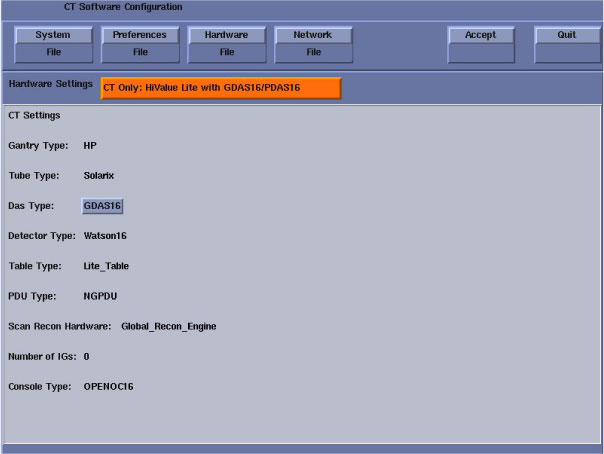
Then select: Hardware to access system hardware configuration.
In the hardware configuration window, select the appropriate hardware configuration for the system. Click OK when done.
note:All optional buttons of the hardware settings must match configuration of site.
Figure 4. Hardware Setting
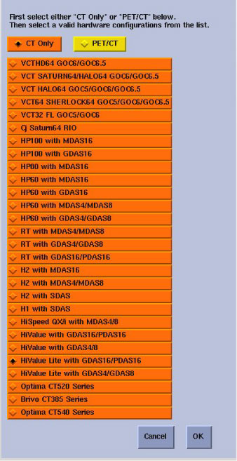
Figure 5. Hardware Configuration Window
 note:
note:Failure to install the correct application software and select the correct system DAS hardware configuration will result in system downtime and DCB circuit board replacement. (This failure will occur after the flash download procedure flashes the firmware.)
-
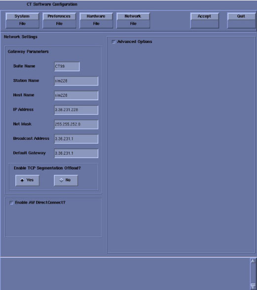
Select: Network to access Network Settings screen.
Figure 6. Network Setting Screen
-
Suite Name - The Suite Name must utilize uppercase letters. It must start with a letter, followed by 3 alphanumeric characters. The total must be four characters long. It is suggested that you choose CT01 for the first scanner (CT02....), unless a different Suite Name is required.
-
Station Name - The Station Name identifies the text that is stored in the DICOM attribute “Station Name” (DICOM TAG 0008,1010) in all CT images created. Some PACS systems may use the Station Name attribute or system tracking for identification of the scanner where the CT images were generated. Typically, the Host Name and Station Name are the same.
note:The Station Name defaults to the Host Name if it is left blank. If entered it:
-
MUST NOT exceed 16 characters
-
MUST only contain the following characters: a through z, A through Z, 0 through 9, - and _
-
MUST have at least one Alpha Character (A-Z or a-z) or Special Character (_ or -)
-
-
Host Name
note:The Host Name identifies the hostname and AE Title of the scanner. It:
-
MUST NOT exceed 16 Characters.
-
MUST only contain the following characters: a through z and 0 through 9
-
MUST have at least one Alpha Character (A-Z or a-z) or Special Character (_ or -)
-
-
IP Address - Site supplied address.
-
Net Mask - Site supplied address.
note:If the hospital backbone IP address is 192.9.220.xx, then the Net Mask must be set to 255.255.255.252.
-
Broadcast Address - Site supplied address.
-
Default Gateway - Site supplied address.
note:Make sure the NUM LOCK button on the keyboard is not active. If it is, deselect it to enable the ACCEPT button in the next step. Failure to deactivate the NUM LOCK results in load issues.
-
At Enable TCP Segmentation Offload?, the default selection is On. In some situation, TCP Segmentation Offload can't work normally. Please select No at this time.
-
If your customer has AW Direct Connect, then select Enable AW Direct Connect?. (Do not configure AW Direct Connect now.)
-
If there is an Internal Option - Internal Subnet setting displayed and checked, then un-check it. (This option might not appear on your system.)
-
Verify with customer’s network administrator if they have NIS. If they do, ensure the Advanced Options and Use NIS? boxes are checked. If they don’t, ensure these selections are not checked.
-
Domain Name: add your name here (get name from customer’s network administrator).
-
Enter the IP Address of Internal Server: add your IP address here (get IP address from customer’s network administrator).
-
-
If your customer wants to synchronize the system time to their NTP server, then select Enable Network Time Protocol, and enter the Primary Server IP address.
-
-
After manually configuring the system, click Accept button at the right corner of the User Interface.
Figure 7. System Configuration Utility - Accept Button
-
An Install INFO pop-up box is displayed, click Yes and return to Applications Software Load, in the Load From Cold (LFC) procedure.
Figure 8. Install INFO