- Topic ID: id_16157698
- Version: 1.0
- Date: Jul 7, 2018 4:26:37 PM
MDAS/GDAS 16 Detector Flex Pinouts
Detector Flexes
The flex lead diagram in Figure 1 show the pin relationship to its associated detector module. Example: 8A16, 22 translates to -> Row 8, A side, Cell 16, Flex pin 22
Figure 1. DAS 16 Backplane Flex Pin Assignments
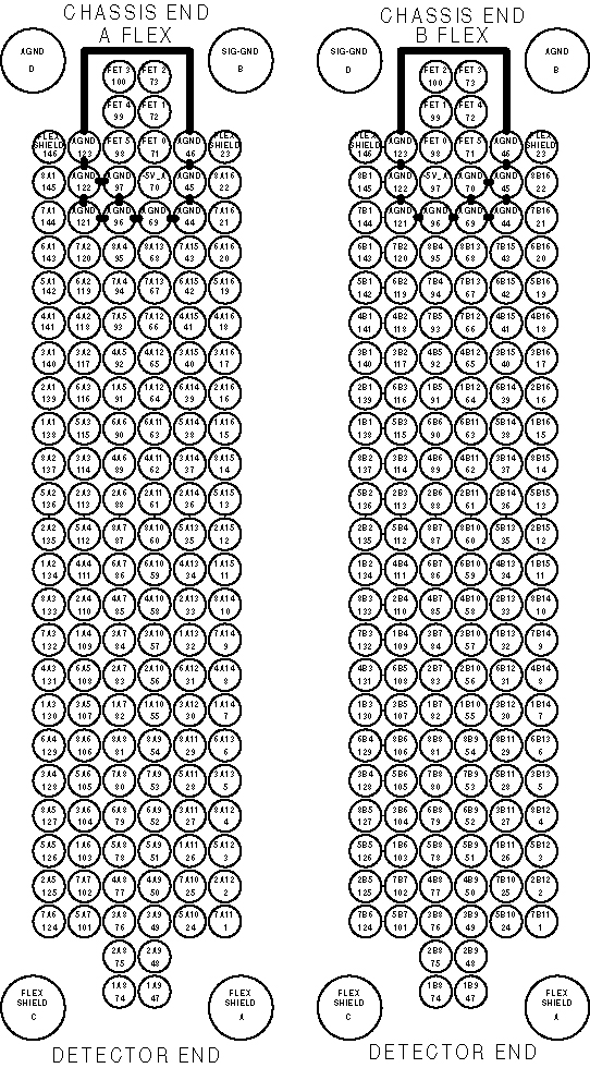
Figure 2 shows the FET control lines, DVSS (- 5vdc bias for detector FETs) and guard band (analog grounds) to prevent random FET settings due to leakage currents.
Figure 2. DAS 16 Detector Flex Lead FET Control Pinout