- Topic ID: id_16158095
- Version: 2.0
- Date: Jun 10, 2020 2:41:58 AM
DASM Settings and LEDs
1 GE Specific Jumper Settings
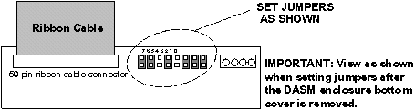
Figure 1. DASM Jumpers
2 GE Specific SCSI Settings
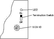
Figure 2. DASM Bottom, Showing SCSI Settings
3 DASM/LCAM Host Control Serial Link (Digital DASM Only)
RS232 serial host control interface, 25-pin D-type connector
-
pin 2 (TX)
-
pin 3 (RX)
-
pin 7 (GND)
A null modem cable may be required (reverses pins 2-3) between some cameras.
-
baud rate = 1200
-
start bits = 1
-
stop bits =1
-
parity = even
-
end of message = CR
-
protocol = ACK/NACK (3M M952)
4 DASM LEDs
DASM green LEDs viewed from front of DASM and air vents at bottom. The “RDY” and “XFR” LEDs only exist on the analog VDB DASM.
-
PWR - on whenever DASM power applied (+5VDC)
-
CPU - flashes idle heartbeat at 1 CPS or indicates CPU activity
-
SCSI - flashes when OC and DASM communicate over the SCSIbus
-
PIF - flashes when the DASM and camera communicate over the serial port
-
RDY - analog VDB only, indicates an image is ready to be “grabbed” by the camera video/analog input port
-
XFR - analog VDB only, indicates an image is being “grabbed” by the camera video/analog input port
5 DASM/LCAM Image Data Interface
RS422/RS485 8-bit digital image data interface, 37-pin D-type connector (3M M952 defacto industry standard digital interface).
-
pixels: 512
-
lines: 512
-
bits/pixel: 8
-
protocol: 3M M952
The gray scale reference bar option at the left of the filmed images is NOT supported by the digital filming interface.