- Topic ID: id_18717918
- Version: 2.0
- Date: Feb 4, 2020 1:38:42 AM
06MW3.5 SW LFC
1 Scope
This LFC (Load from Cold) procedure supports the following GRE/Xtream Operator Console systems:
-
HiSpeed QX/i
-
LightSpeed 1.X
-
LightSpeed 2.X
-
LightSpeed 3.X (4- and 8-Slice)
-
LightSpeed 4.X (16-Slice)
-
LightSpeed 5.X Pro16 (80kw & 100kW) -- MDAS & GDAS
-
LightSpeed 5.X RT -- MDAS & GDAS
-
LightSpeed 5.X (4/8/16-Slice) MDAS & GDAS
2 Preliminary Requirements
2.1 Software to Install
If performing FMI 25365 (GE Healthcare personnel only) or a GRE console upgrade, then retrieve all of the software items listed in this section.
If performing only a re-load-from-cold (re-LFC) of software release 06MW03.5, then retrieve the software set, p/n 5164732.
Software collector called “GRE/Xtream Q1 2006 Software Set,” p/n 5164732, contains the following items:
The Xtream Serial-Over-Lan Service Software is not used during the LFC unless instructed via a pop-up message box "SOL Service - ...run the Serial Over LAN Service CD...". This CD is loaded directly into the DARC Node. Then press the reset (or cycle power) at the front panel of the DARC Node as required. This CD will auto-eject when the SOL load process is complete.
(For GE Healthcare Personnel Only) FMI 25365 kit and IRIX to Linux/GRE console upgrade kits contain:
2.2 Hardware-Related Prerequisites for GOC2/GOC3/GOC4
2.2.1 Ensure Both SDDA Drives Are Functioning
Open Unix Shell and type the following:
-
{ctuser@hostname} rsh darc
-
[ctuser@darc] cat /proc/scsi/scsi
note:Output should look similar to the following. Look for two drives. If there are NOT two drives, troubleshoot.
Attached devices:
Host: scsi0 Channel: 00 Id: 00 Lun: 00
Vendor: SEAGATE Model: ST336753LW Rev: 0006
Type: Direct-Access ANSI SCSI revision: 03
Host: scsi0 Channel: 00 Id: 01 Lun: 00
Vendor: SEAGATE Model: ST336753LW Rev: 0006
Type: Direct-Access ANSI SCSI revision: 03
-
Close the Unix Shell.
2.2.2 SCSI Tower Drive Verification
Perform this recommended procedure to check DVD or MOD functionality prior to performing a LFC.
-
Verify the SCSI Tower DVD-RAM power is applied and the green LED at front of tower is lit.
-
Verify the SCSI Tower terminator LED is lit (located at the rear).
-
Verify the Host Computer DVD-ROM drive does not have a disk in it.
-
Open a Unix Shell and verify the SCSI Tower components are present (two examples are shown below, but may not match your SCSI Tower configuration):
{ctuser@hostname} scsistat
Example #1:
Device 0 00 Direct-Access SEAGATE ST336753LW FW Rev: HPS2 OS 36 GB
Device 1 01 Direct-Access SEAGATE ST373453LW FW Rev: HPS2 73 GB Image
Device 1 02 Direct-Access SEAGATE ST373453LW FW Rev: HPS2 73 GB Image
Device 2 03 Optical Device SONY SMO-F551-SD FW Rev: 1.04 SCSI Tower Sony MOD
Device 2 04 CD-ROM MATSHITA DVD-RAM LF-D521 FW Rev: A109 SCSI Tower DVD-RAM
Example #2:
Device 0 00 Direct-Access SEAGATE ST336753LW FW Rev: HPS3
Device 1 01 Direct-Access SEAGATE ST373453LW FW Rev: HPS3
Device 1 02 Direct-Access SEAGATE ST373453LW FW Rev: HPS3
Device 2 03 Optical Device SONY SMO-F551-SD FW Rev: 1.03 SCSI Tower Sony MOD
Device 2 04 CD-ROM HITACHI DVD-RAM GF-2050 FW Rev: E372 SCSI Tower Hitachi DVD-RAM
Device 4 00 CD-ROM HL-DT-ST DVD-ROM GDR8163B FW Rev: 0B15
-
(For Linux Consoles Only) DVD Drive Verification:
-
Create a temporary testing file:
{ctuser@hostname} su -
Password: <password>
{root@hostname} dd if=/dev/urandom of=/tmp/foo bs=1024 count=50k
51200+0 records in
51200+0 records out
-
Ensure the temporary testing file was created:
{root@hostname} ls -al /tmp/foo
-rw-r--r-- 1 root root 52428800 May 10 11:55 /tmp/foo
(”5242880” represents the file size.)
-
Calculate the checksum for the local temporary file.
note:These numbers will change every time you generate a new file.
{root@hostname} sum /tmp/foo
45731 51200
note:1st # = checksum (FE should write this down to use for comparison later)
2nd # = size of file checksum'd
Checksum File Size in kilobytes
-------- ----------------------
45731 51200
-
Insert DVD into SCSI Tower.
Data on inserted DVD will be destroyed.
-
Create a filesystem on the DVD by typing the following:
{root@hostname} mkfsDVD
----------------------------------------------------------
*** CAUTION ***
A filesystem already exists on this DVD.
This utility will create a new file system on the DVD. In turn it will wipe clean any existing files and data. Make sure you have the correct DVD media in the correct DVD drive.
Do you wish to proceed? [n] y
Making file system. This will take approximately 3-5 minutes
-----------------------------------------------------
-
Mount the DVD:
{root@hostname} mountDVD
Mounting DVD
-
Copy the file to the target device:
{root@hostname} cp /tmp/foo /DVD && sync
-
Unmount the drive & eject the DVD to ensure the system's cache is flushed. This is required to calculate the checksum properly.
-
{root@hostname} unmountDVD
DVD is now unmounted.
-
Eject the DVD
-
Reinsert the DVD
-
Remount the target device, using mountDVD.
-
-
Generate checksum on file in DVD drive:
{root@hostname} sum /DVD/foo
45731 51200
-
Verify (compare) the file's checksum calculated by the host console matches the checksum calculated by the drive.
-
{root@hostname} unmountDVD
DVD is now unmounted.
-
Eject the DVD
-
-
(For IRIX Consoles Only) MOD Drive Verification:
-
Create a temporary testing file:
{@hostname} su -
Password: <password>
{root@hostname} dd if=/dev/urandom of=/tmp/foo bs=1024 count=50k
51200+0 records in
51200+0 records out
-
Ensure the temporary testing file was created:
{root@hostname} ls -al /tmp/foo
-rw-r--r-- 1 root root 52428800 May 10 11:55 /tmp/foo
(”5242880” represents the file size.)
-
Calculate the checksum for the local temporary file.
note:These numbers will change every time you generate a new file.
{root@hostname} sum /tmp/foo
45731 51200
note:1st # = checksum (FE should write this down to use for comparison later)
2nd # = size of file checksum'd
Checksum File Size in kilobytes
-------- ----------------------
45731 51200
-
Insert MOD into SCSI Tower.
Data on inserted MOD will be destroyed.
-
Create a filesystem on the target device (MOD) by typing the following:
{root@hostname} mkfsMOD
----------------------------------------------------------
*** CAUTION ***
A filesystem already exists on this MOD.
This utility will create a new file system on the MOD. In turn it will wipe clean any existing files and data. Make sure you have the correct MOD media in the correct MOD drive.
Do you wish to proceed? [n] y
Making file system. This will take approximately 3-5 minutes
-----------------------------------------------------
-
Mount the MOD:
{root@hostname} mountMOD
Mounting MOD
-
Copy the file to the target device:
{root@hostname} cp /tmp/foo /MOD && sync
-
Unmount the drive & eject the MOD to ensure the system's cache is flushed. This is required to calculate the checksum properly.
-
{root@hostname} unmountMOD
MOD is now unmounted.
-
Eject the MOD
-
Reinsert the MOD
-
Remount the target device, using mountMOD.
-
-
Generate checksum on file in MOD drive:
{root@hostname} sum /MOD/foo
45731 51200
-
Verify (compare) the file's checksum calculated by the host console matches the checksum calculated by the drive.
-
{root@hostname} unmountMOD
MOD is now unmounted.
-
Eject the MOD
-
2.3 Software Related Prerequisites
 |
|
|
|
Determine the version of software loaded on the system by one of the following methods:
-
Open a Unix Shell and type one of the following:
check_config
- OR -
swhwinfo -all
-
Look at the Common Service Desktop Home Page.
Software version 405L.8 and 308L.8 were deployed by the last globally-distributed FMIs 25338 & 25337, respectively.
2.4 Information Capture
2.4.1 IRIX and Linux Information Capture
-
Record Autovoice Volume control settings (ALT-F3 by Toolchest, upper right corner).
-
Write down all of the system INFO information on the reconfig screens, including the network information (use the appropriate information sheet, found in GRE/Xtream Operator Console Information Sheets). You cannot restore the INFO file during the Load from Cold on the new console.
-
Verify and record specific system hardware configuration.
-
Open a shell and type the following:
{ctuser@hostname} cat /usr/g/config/INFO
-
Record screen information in Console Information Sheets.
For an example output, see Example Config/INFO Output.
-
-
If the console has Connect Pro installed, write down the information when you run installhisris so it can be entered on the new console when installing the Connect Pro option.
-
With Application Software UP, record gantry revolutions and tube usage:
-
Launch Common Service Desktop.
-
Record the Next Patient Exam Number.
-
Capture gantry revs located in the upper right corner of the Home Page.
This value will be entered after “Restore System State”.
-
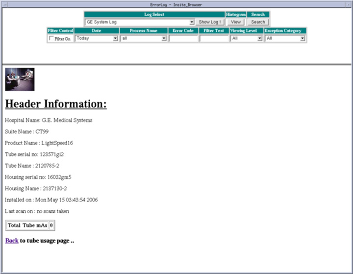
For each tube, record Tube Usage mAs, Tube Model #, Tube Serial #, and Tube Install Date.
For the current tube, also record Housing Name, Housing Serial #, and Tube Name.
-
Select Common Service Desktop.
-
Select Error logs.
-
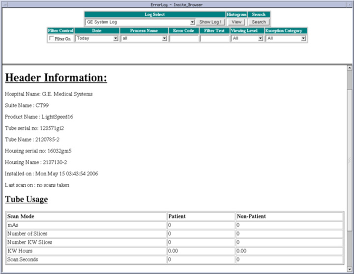
Select Tube Usage.
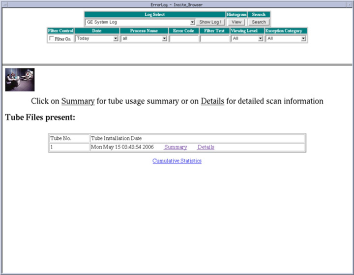
-
Select Summary and record the information.
-
Go back and select Details to record Scan Seconds.
-
Do this for all tubes listed.
-
Close the window.
-
-
-
Close the Service Desktop window in the upper left corner of the screen.
2.4.2 Linux Only Information Capture
If your system does NOT have “Exam Split” option, skip this section.
Perform these steps before powering down your current GOC2, GOC3 or GOC4 Operator Console:
-
Open a Unix Shell and type the following:
-
{ctuser@hostname} su –
-
Password: <password>
-
[root@hostname] ls –l ~ctuser/ves/.hesMode
note:There are no spaces in the phrase ~ctuser/ves/.hesMode
-
-
Examine the results.
-
If the results are similar to:
-rw-r--r-- 1 ctuser users 0 Apr 3 12:43
/usr/g/ctuser/ves/.hesMode
Then HES (Hard Exam Split) mode is configured.
-
If the results show ‘No such file or directory’, then VES (Virtual Exam Split) mode is configured.
-
-
Record Exam Split Mode (Hard or Virtual). This info will be used during the LFC Options Installation.
-
Close the Unix Shell
2.4.3 HIPAA Information
Systems upgrading from software 04MW44.9 or previous versions will need to rebuild the HIPAA files. Before proceeding, record the User Names (that operators log in as), groups, and permissions used. User passwords will need to be reset after the software load.
3 Procedure
|

|
|
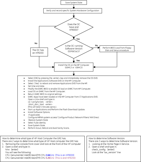
3.1 Steering Guide
Figure 1. Steering Guide Flowchart
3.2 Save System State
New tasks are included in this SW release These task will generate data that needs to be saved to the system state DVD. Follow the save and restore procedures throughout this document precisely or valuable information may be lost.
Perform one of the following methods to Save System State, depending on current Operator Console type
-
IRIX systems Save System State for Upgrading to Linux (see IRIX Systems Upgrading to Linux - Save System State).
-
For Linux systems, Save System State as listed in Linux Systems - Save System State.
3.2.1 IRIX Systems Upgrading to Linux - Save System State
|
|
The original “Save System State” MOD will be used only if the customer wants to revert back to the original IRIX-based SW.
Perform the following steps on the IRIX console before powering down and installing the GRE/Xtream Operator Console.
-
Save System State (twice) to an MOD on the IRIX console before installing the new GRE/Xtream Operator Console.
-
Insert the MOD into the SCSI Tower MOD drive.
-
Select: Service Desktop.
-
If reloading software, select: UTILITIES. If upgrading from earlier version software, select: PM.
-
Select: System State.
-
Select ALL to save all data.
-
Select SAVE.
-
If applicable, select OK when the following message appears: System State Media Status: Please insert a DVD or MOD into the drive and press Save again.
-
When completed select DISMISS.
-
For the original MOD, label the MOD as “Final IRIX Conversion Release”.
-
Repeat Steps a-j, for the second “Save System State”, using a new MOD, and label with the same SW release that is found on the DVD label.
-
-
Modify System State MOD
-
Insert System State MOD into the drive.
-
Open a Unix Shell and type the following:
-
{ctuser@hostname} su –
-
Password: <password>
-
[root@hostname] mountMOD
-
[root@hostname] cd /MOD/service_mod_data/system_state
-
[root@hostname] chmod 666 *bb .epdlog
(change permissions on tube usage & edit patient data files)
-
[root@hostname] rm -f *.stats
(removes runtime stats on non-HPOWER systems)
-
[root@hostname] rm -f iipBackupGen2.tar.Z
(removes IIP “tar ball” files à not used by new IIP)
-
[root@hostname] rm -f Voxtool.prefs
(removes Voxtool preferences ⇒ new Voxtool application uses new set of preferences)
-
[root@hostname] rm -f smartscore.tar.gz
(removes SmartScore files ⇒ SmartScore not applicable to PathFinder / not supported by PathFinder software)
-
[root@hostname] rm -f vxtlBackup.tar
(removes VoxTool files ⇒ new Voxtool application uses new set of files)
-
Remove VoxtoolPrefs/* and CT_PerfusionPrefs/* files
-
[root@hostname] rm -f movierx*
(removes Direct 3D preferences that the customer cannot edit)
-
[root@hostname] rm -f *.flm
-
[root@hostname] rm -f *.pro
-
[root@hostname] rm -f *.vrp
-
[root@hostname] rm -f *.adv
-
[root@hostname] rm -f *.adv.research
-
[root@hostname] rm -f *.disp
-
[root@hostname] rm -f *.disp.research
-
[root@hostname] cd
-
[root@hostname] unmountMOD
-
-
Close the Unix Shell.
-
3.2.2 Linux Systems - Save System State
|
|
The original “Save System State” will be used only if the customer wants to revert back to the original SW.
Perform these steps before powering down your current GOC2, GOC3 or GOC4 Console:
-
Insert the DVD-RAM into the SCSI Tower DVD drive.
-
Select Service Desktop
-
If reloading software, select: UTILITIES. If upgrading from earlier version software, select: PM.
-
Select System State
note:System State Save may be under Utilities or PM.
-
Select ALL to save all data.
-
Select SAVE
-
If applicable, select OK when the following message appears: System State Media Status: Please insert a DVD or MOD into the drive and press Save again.
-
When completed select DISMISS.
-
For the original DVD, label the DVD as “Linux System State Backup”.
-
Repeat Steps 1-8, for the second “Save System State”, using a new DVD, and label with the same SW release that is found on the DVD label.
-
Close the Service Desktop window in the upper left corner of the screen.
-
Sites performing the next sub-section should not remove the DVD-RAM from the SCSI Tower DVD-RAM drive.
3.3 Install GRE/Xtream Console
This section only applies to GOC1 (IRIX) and GOC2 (Linux-Pegasus) Operator Console upgrades.
-
Power-down the GOC1 or GOC2.
-
Install the new GRE/Xtream (Linux) Operator Console.
You will be using your existing SCIM/Keyboard, monitors and mouse, unless you received a new SCIM or mouse. You will receive a new trackball that must be used on the new Operator Console. Your old trackball will no longer work.
Install the new SCSI Tower (DVD-ROM drive and MOD drive).
Install the new trackball (it is connected at the rear of the Operator Console near the connections for the keyboard and mouse). The extension cable for the trackball is already connected to the USB port at the rear of the Host Computer.
When you power up the GRE/Xtream (Linux) Operator Console:
-
Verify the SCSI cable is connected to the SCSI Tower
-
Verify the SCSI Tower power is applied and green LED on front is lit.
-
Verify the SCSI Tower terminator LED is lit (located at the rear).
See the Installation Instructions that came with the new Operator Console.
-
3.4 Determine Whether Host BIOS Must Be Set Up
3.4.1 Determine Type of Host Computer
Determine type of Host computer:
-
Remove the console front cover and look at the front of the Host Computer for host type.
-
Open a shell and type: hinvEnter
You will see one of the following:
(For HP8000) CPU: GenuineIntel Intel(R) Xeon(TM) CPU 2.66GHz
(For HP8200) CPU: GenuineIntel Intel(R) Xeon(TM) CPU 3.20GHz
3.4.2 Determine Software Version
Refer to software version recorded earlier in Software Related Prerequisites.
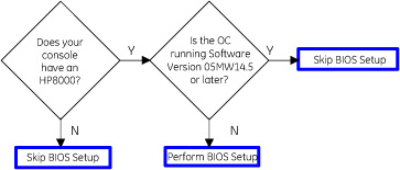
3.4.3 Host Computer BIOS Setup Decision Tree
Using the information gained from the above two sections, follow the flowchart below, to determine whether or not you need to perform the BIOS Setup.
(Clicking on the blue boxes will advance to the proper section of this document.)
Figure 2. BIOS Setup Decision Tree
3.5 HP xw8x00 PC BIOS Setup
(For Systems with an HP xw8200 PC) Proceed toLoad from Cold Installation Procedures (LFC).
(For Systems with an HP xw8000 PC) Prepare to verify/load HP xw8000 PC BIOS (JQ.W1.13US) and setup the BIOS. Follow all of the procedures in this section.
3.5.1 Verify/Load Host PC BIOS From Floppy Disk “BIOS v1.13 for HP 8000 Host Console PC-only Floppy”
-
Determine Host Computer BIOS version
-
Open a Unix Shell and halt the system:
-
{ctuser@hostname} halt
-
The Operator Console monitor will display a System halted message when it is acceptable to power OFF the Operator Console.
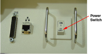
Power Operator Console ON at the front switch.
-
-
At the hp invent screen on the monitor, press F2.
-
Verify the Main menu screen is displayed.
-
View BIOS Version, and verify it is JQ.W1.13US or greater.
-
If it is the correct version, go to Set Up the xw8000 Host BIOS - Main Setup Screen
-
If it is NOT the correct version, proceed with Step 2 (below).
-
-
-
Remove Operator Console front cover.
-
Insert BIOS floppy disk in Host Computer.
-
Reboot Host Computer. (Front power button on Host computer.)
-
When the BIOS Setup Utility screen is displayed, select Option A, Flash BIOS by typing A and pressing the Enter key.
The BIOS will begin to load from floppy. Allow the BIOS to load completely.
-
Reboot, press any key.
The “Press any key to reboot” message will be displayed when the BIOS-flashing is complete.
Remove BIOS floppy disk from the drive to prevent boot-up from floppy.
-
Press F2 to interrupt the boot-up sequence to edit BIOS settings.
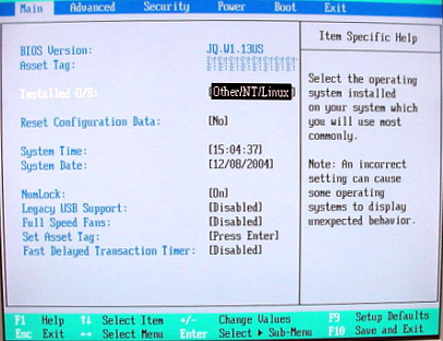
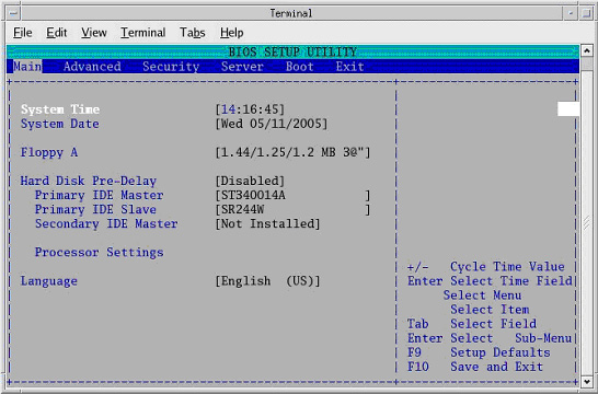
3.5.2 Set Up the xw8000 Host BIOS - Main Setup Screen
Changes can be made by cursor-selecting the parameter, then using the “+” and “-“ buttons to toggle its value.
The Main setup screen is shown in Figure 3. Confirm that all parameters are set as shown.
Figure 3. Main Setup Screen
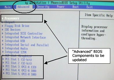
3.5.3 Set Up the xw8000 Host BIOS - “Advanced” Settings
-
From the Main Menu screen, use arrow key to select (move to) Advanced to view the Advanced setup screens.
-
The Advanced BIOS setup screen is shown below. The BIOS components that will be updated in the next steps are highlighted.
-
From the Advanced Menu screen, use arrow key to select (move to) Processors and press Enter.
-
Set all Processors parameters as shown below.
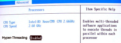
-
When Processors setup is complete, press Esc key to return to the Advanced menu.
-
From the Advanced Menu screen, use arrow key to select (move to) PCI Slot 1 and press Enter.
-
Set all Advanced-PCI Slot 1 parameters as shown below.
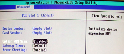
-
When Advanced-PCI Slot 1 setup is complete, press Esc key to return to the Advanced menu.
-
From the Advanced Menu screen, use arrow key to select (move to) PCI Slot 2 and press Enter.
-
Set all Advanced-PCI Slot 2 parameters as shown below.
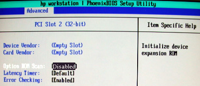
-
When Advanced-PCI Slot 2 setup is complete, press Esc key to return to the Advanced menu.
-
From the Advanced Menu screen, use arrow key to select (move to) PCI Slot 3 and press Enter.
-
(For Adaptec) Set all Advanced-PCI Slot 3 parameters as shown below.
(For QLogic) Device Vendor and Card Vendor will read 1077H. Set all Advanced-PCI Slot 3 parameters as shown below, EXCEPT Option ROM Scan, which should be set to [Enabled].
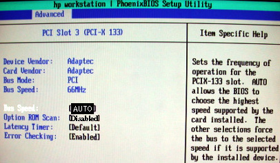
-
When Advanced-PCI Slot 3 setup is complete, press the Esc key to return to the Advanced menu.
-
From the Advanced Menu screen, use arrow key to select (move to) PCI Slot 4 and press Enter.
-
Set all Advanced-PCI Slot 4 parameters as shown below.
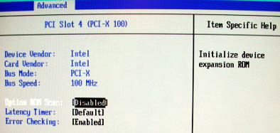
-
When Advanced-PCI Slot 4 setup is complete, press Esc key to return to the Advanced menu.
-
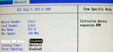
From the Advanced Menu screen, use arrow key to select (move to) PCI Slot 5 and press Enter.
-
Set all Advanced-PCI Slot 5 parameters as shown below.
-
When Advanced-PCI Slot 5 setup is complete, press the Esc key to return to the Advanced menu.
3.5.4 Set Up the xw8000 Host BIOS - “Power” Tab
-
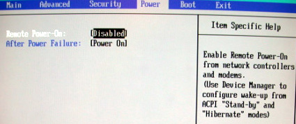
From the Main Menu screen (shown below), use arrow key (move) to select Power.
-
Setup POWER as shown below.
-
When POWER setup is complete, press the Esc key to return to the Main menu.
3.5.5 Set Up the xw8000 Host BIOS - “Boot” Tab
-
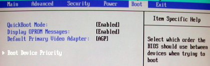
Setup BOOT: From the Main Menu screen, use arrow key to select (move to) Boot.
-
Set all Boot parameters as shown below.
-
Arrow-select (move) to Boot Device Priority and press the Enter key.
-
Setup BOOT DEVICE PRIORITY as shown below.
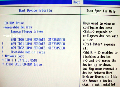 note:
note:The CD-ROM Drive may be missing. Ignore this.
note:The ! key disables/enables devices.
-
When BOOT DEVICE PRIORITY setup is complete, press the Esc key to return to the Main menu.
-
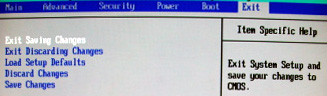
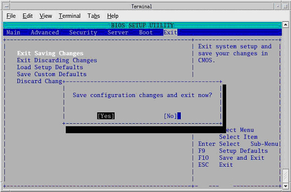
Save BIOS settings as shown in the two figures below.
-
From Main menu, arrow to (move to) EXIT.
-
Select Exit Saving Changes and Enter key.
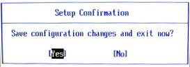
-
Select YES and Enter key to “Save configuration changes and exit now”.
-
3.5.6 Set Up the xw8000 BIOS - End
Host BIOS setup is complete.
3.6 Load from Cold Installation Procedures
Use the procedures in this section to perform a LFC.
3.6.1 OS Installation on Host Computer, “Linux Operating System Version 4.3.16” DVD
System State SAVE must be performed before shutting down apps (Application Software).
During the OS load you need to select "ignore" twice when it complains about I/O errors with a SCSI device. These messages will occur with systems without a DASM:
Input/output error during read on /dev/sd?
Input/output error during write on /dev/sd?
-
Remove the GRE/Xtream Operator Console's front cover.
-
Remove the Hospital Backbone Ethernet cable from the Console Bulkhead Assembly, located at the rear of the Operator Console.
-
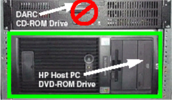
Insert the OS disk into the DVD-ROM drive on the Host Computer. See the following illustration.
-
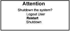
Select one of the following methods to re-power the Operator Console:
-
If Applications are up:
-
Select the Shut Down button.

-
Select Restart then OK to restart the system.
-
-
If Application Software is down, at the toolchest open a Unix Shell and type:
-
{ctuser@hostname} halt
-
The Operator Console monitor will display a System halted message when it is acceptable to power OFF the Operator Console.
-
Power OFF the Operator Console at the front panel switch.
-
Wait 30 seconds to allow the disk drive to settle; then power ON the Operator Console at the front panel switch.
-
-
-
As the computer restarts, the booting process messages appear. After the booting process completes, the boot: prompt appears.
-
At the boot prompt, type the following depending on system type:
(For English Keyboard only) GEHC2 Enter
(For International Command only) iGEHC2 Enter
note:The Console Operating System load takes approximately 15 minutes. If the boot: prompt does not appear, then either the DVD-ROM is bad or the Console Operating System DVD is not installed in the drive. Typing GEHC will result in both scan and display being on one monitor and require a LFC.
-
After the OS is loaded, a red button appears and displays Reboot.
-
Remove the OS disk, when it ejects.
-
Press ENTER to reboot.
-
The Host Computer reboots.
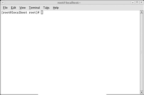
note:Do not insert the Application disk into the Host Computer until the system reboots and the [root@localhost] window appears, displaying the [root@localhost root]# prompt.
3.6.2 Application SW Load on the Host Computer, “06MW3.5 Applications, HOST & DARC, Q2 2006 Common Platform Rls” DVD-ROM
There is a single Application DVD used for both the Host Computer and the DARC. All applications software will be loaded to the Host Computer during this process.
|
|
-
After the Host Computer reboots, verify that the window appears with the [root@localhost root]# prompt.
-
In the root@localhost Window, verify the SCSI Tower MOD and DVD are present:
[root@localhost root]# cat /proc/scsi/scsi
-
Insert the Application DVD into the DVD-ROM drive on the Host Computer. See the illustration below.
-
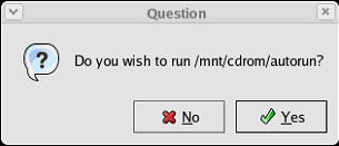
After approximately 15 seconds a pop-up box appears:
-
Select Yes.
note:If the pop-up box Question does not appear after two minutes, type the following and wait approximately one minute for the pop-up box to appear.
mount /mnt/cdrom Enter
/mnt/cdrom/autorun Enter
-
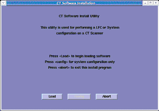
After approximately 15 seconds, an Installation Utility window appears. (See illustration, below.)
-
Select Load. A prompt message appears asking if you wish to load the INFO file from the System State DVD.
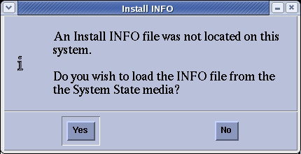
-
System State DVD:
-
If you do NOT have a System State or the System State is unusable, select No.
-
If you have a System State DVD, select Yes. When prompted, ensure the System State DVD is in the DVD drive in the SCSI Tower (on top of the console), and then select ok.
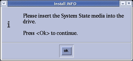
An “unMount media” pop-up may appear. No action is required.
-
-
Select the System tab.
See example System Settings screen, below.
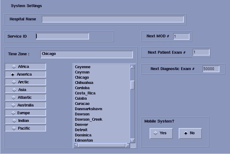
-
Verify that the Next Patient Exam # on the System Settings screen is the value restored from Save System State. Otherwise, set to 1.
-
Verify that the proper Time Zone is selected
Select/enter information as required for your system configuration.
-
Select the Preferences tab.
See the illustration below, for an example Preference Settings screen.
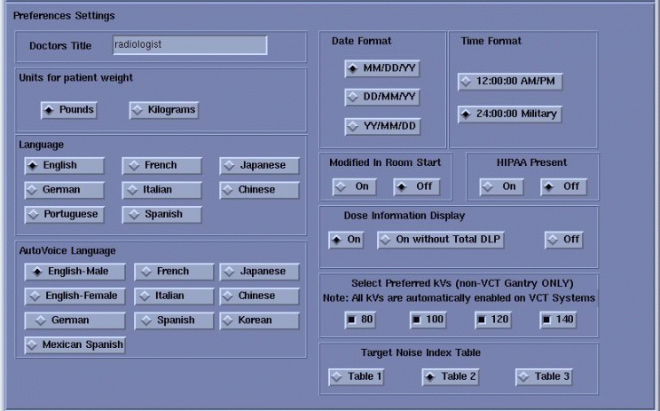
-
Select the units for patient weight.
-
Select Language: (English or other).
-
Select Preferred FastCal KV - select the kV to be calibrated during FastCal. These kVs should include all kVs that the site uses for patient scanning.
-
Select Target Noise Index Table.
(Default is Table 2.)
-
Verify proper Date Format is selected.
-
Verify proper Time Format is selected.
-
Select AutoVoice Language.
-
Verify Modified in Room Start is set to Off. Sites in Japan must be set to On.
-
Set HIPAA Present to OFF unless the customer requests HIPAA to be ON.
-
Select the site preferred Dose Information Display option for the site to use in monitoring calculated Patient Dose (on view edit screen):
Select ON (full DOSE Display) or previous Customer setting.
note:A scroll bar below this menu may be present. It contains the System Information from the INFO file System State.
-
Select the Hardware tab.
-
Select Hardware Parameter Selection.
An example Select Hardware Configuration screen is shown below.
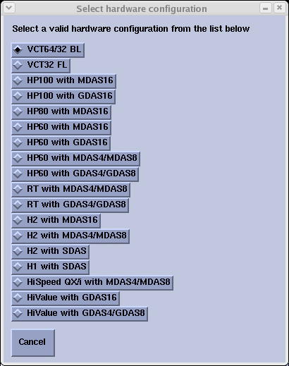 note:
note:FAILURE TO INSTALL THE CORRECT APPLICATION SOFTWARE AND SELECT THE CORRECT SYSTEM DAS HARDWARE CONFIGURATION WILL RESULT IN SYSTEM DOWNTIME AND DCB CIRCUIT BOARD REPLACEMENT. (THIS FAILURE WILL OCCUR AFTER THE FLASH DOWNLOAD PROCEDURE FLASHES THE FIRMWARE.)
Select your System types HW Parameters, and close this window.
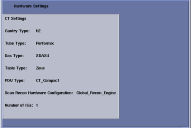
-
On the Hardware Settings screen, the Number of IGs is set to 1.
-
Select the Network tab.
See example Network Settings screen, below.
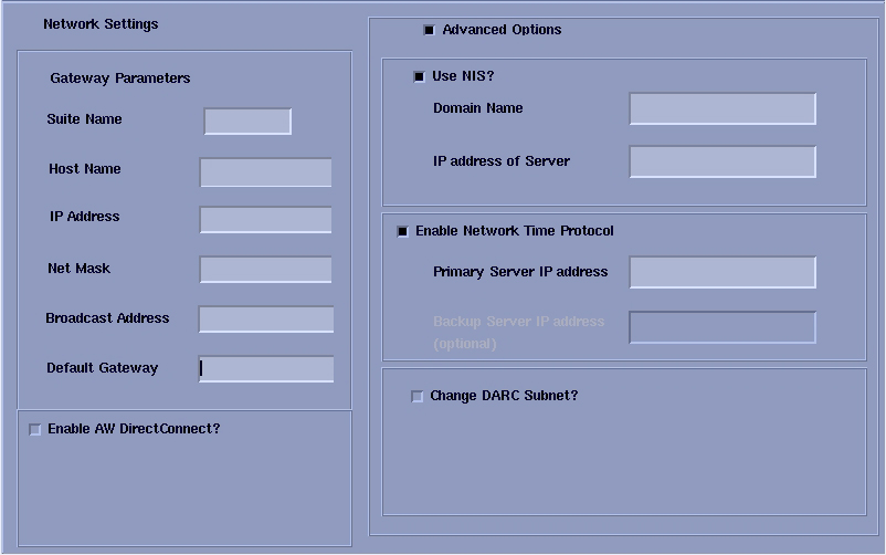
-
Configure Network Settings:
-
Suite Name: Add your name here.
note:The Suite Name must start with a letter, followed by 3 alphanumeric characters. Total must be four characters long. The name of the OC interface is <Suite Name>_oc within the scanner's subnet. It is suggested that you choose CT01 as its name, unless a different Suite Name is required.
-
Host Name: Add your host name here.
note:The Host Name identifies the hostname and AE Title of the scanner. It:
-
MUST NOT be <Suite Name>_oc or <Suite Name>_OC.
-
MUST NOT exceed 16 Characters.
-
MUST only contain the following characters: a through z, 0 through 9, - and _
-
-
IP Address - Site supplied address.
-
The following procedure should be performed if your customer Ethernet hospital backbone begins with 172.16.0.xx, OR if the scanner will connect to a device with an IP address of 172.16.0.xx.
-
If hospital backbone starts with 172.16.0.xx and this is a first time install, continue and complete the software load on the HOST and DARC. When the DARC applications load is complete the DARC subnet can be changed by running “reconfig”. During reconfig, check the Change DARC subnet box, and enter the following value: 169.254.0
-
If the hospital backbone starts with 172.16.0.xx, and the DARC subnet was already changed, continue and complete the software load on the HOST and DARC.
-
If the DARC subnet was already changed and needs to be set to the 172.16.0 subnet continue and complete the load on HOST and DARC and run reconfig to change the DARC subnet.
-
-
Net Mask - Site supplied address.
note:If the hospital backbone IP address is 192.9.220.xx, then the Net Mask must be set to 255.255.255.252.
-
Broadcast Address - Site supplied address.
-
Default Gateway - Site supplied address.
note:Make sure the NUM LOCK button on the keyboard is not active. If it is, deselect it to enable the ACCEPT button in the next step. Failure to deactivate the NUM LOCK results in load issues.
-
If your customer has AW Direct Connect, then select Enable AW DirectConnect?. Complete the LFC, making certain to configure this feature in AW Direct Connect. (Do not configure AW Direct Connect now.)
-
If there is an Internal Option - Internal Subnet setting displayed and checked, then un-check it. (This option might not appear on your system.)
-
Verify with customer’s network administrator if they have NIS. If they do, ensure the Advanced Options and Use NIS? boxes are checked. If they don’t, ensure these selections are not checked.
-
Domain Name: add your name here (get name from customer’s network administrator).
-
Enter the IP Address of Internal Server: add your IP address here (get IP address from customer’s network administrator).
-
-
If your customer wants to synchronize the system time to their NTP server, then select Enable Network Time Protocol, and enter the Primary Server IP address.
-
-
Select the ACCEPT button at the right corner of the User Interface.
-
An Install INFO pop-up box is displayed.
See the following illustration, for a typical Install INFO message (the Install INFO message is different for each system configuration).
-
Select yes, if correct, and wait for system to reboot.
note:If the information is not correct, select the NO button. This returns you to the Hardware screen. Select the Hardware Parameters Selection button and select the correct system configuration from the displayed list. Select the Accept button again, followed by the YES button on the Install INFO pop-up to accept the new hardware configuration.
-
The following pop-up message appears:
Please make sure the CT Application SW is in the drive - the system will be rebooted.
No action is required for this pop-up. The system will automatically reboot after approximately 10 seconds if the OK button is not selected.
note:Do not remove the Apps DVD from the Host Computer until instructed to do so.
-
As the system reboots, the following shell Installation screen appears and the application software starts loading.
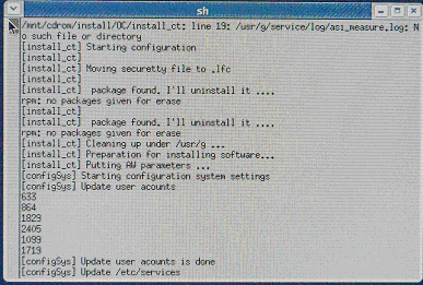
-
STOP. When the system prompts you to reboot (after approximately 13 minutes), DO NOT answer Yes immediately.
Before selecting Yes to reboot, the following command line (next step) must be entered to prevent possible trackball issues in the future. This step should eliminate lengthy downtime due to loss of trackball functionality.
-
In the terminal window that is already open, as root, type the following:
note:X11 = X eleven
root@hostname cp /etc/X11/xorg.conf /etc/X11/xorg.conf.clean
root@hostname cp:overwrite ‘etc/X11/xorg.conf.clean’? y
To verify that command was successful, complete the following command and verify that Creation date and size of xorg.conf.clean and xorg.conf are identical to each other. They may be a different size than listed below. You should get a table similar to the one listed below. The bottom two files are not significant.
root@hostname cd /etc/X11
root@hostname ls –al xorg.conf*
Permissions owner group size Creation date File Name
-----------------------------------------------------------------------------
-rw------- 1 root root 2683 Jun 5 14:46 xorg.conf
-rw------- 1 root root 2683 Jun 5 14:46 xorg.conf.clean
-rw-r--r-- 1 root root 2212 Apr 13 15:34 xorg.conf.lfc
-rw-r--r-- 1 root root 2216 Apr 13 15:33 xorg.conf.orig
-
Now reboot by selecting Yes in the window that opened previously. The system is going down for reboot NOW.
 note:
note:During the reboot of the console, a message may appear to the effect that the system was not able to determine what the tube type was and to run the TIC tool. This message should be ignored.
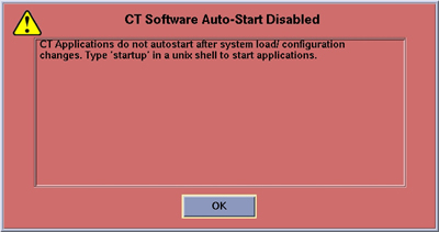
-
After approximately 3 minutes, a pink pop-up box appears, stating CT Software Auto-Start Disabled. In this box, select OK.
-
Press the button on the DVD-ROM drive to remove the Apps DVD from the Host Computer.
3.6.3 Confirm Host PC Software
Confirm the Host Computer Software type. Output of the following commands MUST BE EXACT.
-
Open a Unix Shell and type the following to see software and hardware Config information:
{ctuser@hostname} cd /usr/g/bin
{ctuser@hostname} swhwinfo
06MW03.5. <hardware revision info here>
Example: 06MW03.5.H2_P_S4_G_Zeus
-
Confirm that the swhwinfo results match the software revision shown on the Applications Disk.
-
If the revisions match, continue with this procedure.
-
If the revisions do NOT match, reload the software (Load from Cold Installation Procedures).
-
-
Type: cat /GEHC*
Release: GEHC/CTT Linux 4.3.16
Built: Tue Jul 12 12:29:10 CTD 2005
-
Confirm that the cat result matches the Operating System version shown on the OS disk.
-
Close the Unix Shell.
3.6.4 Load TubeUsageConversion Patch onto the System
This patch is required when upgrading from a previous version of software to 06MW03.5. When RE-loading 06MW03.5 over itself or loading a BrightSpeed with 06MW3.5, it is not necessary to load this patch or run the Tube Usage Conversion Tool later in the procedure.
-
Insert the “Tube Usage Patch for 06MW03.5,” CD-ROM (p/n 5172979) into the HOST DVD Drive.
-
Open a Unix Shell and type the following:
-
{ctuser@hostname} su -
-
Password: <password>
-
[root@hostname] mount /mnt/cdrom
-
[root@hostname] cd /mnt/cdrom
-
[root@hostname] ./install_patch –p GEMS-CT-PFM3-TUBEUSAGE-1-1.i386.rpm
Output from the patch install will state “Installing GEMS-CT-PFM3-TUBEUSAGE-1-1.i386” and end in the text “******POST_INSTALL******”
-
[root@hostname] cd /
-
[root@hostname] umount /mnt/cdrom
-
-
Remove the CD from the Drive
-
Close the Unix Shell.
3.6.5 Change DARC BIOS Boot Order Settings - Enable OS Load on DARC from PC
This section describes the steps necessary to change the DARC Node BIOS to enable the OS load onto DARC Node from the Host Computer. The DARC Node Boot Order BIOS is modified before the DARC Node OS load, and must be returned to original settings after the DARC Node OS load for proper normal operation.
Be patient. Telnet response may be slow.
-
Open a Unix Shell and type the following:
-
{ctuser@hostname} su -
-
Password: <password>
-
[root@hostname] service cliservice start
-
[root@hostname} telnet localhost 623
-
At Server Prompt type: darc
-
username Enter
-
password Enter
Login successful
-
dpccli> reset
ok
dpccli> console
-
-
Interrupt the DARC boot process to enter the BIOS Setup mode. When the message “Press <F2> to enter setup” appears, press F2.
note:F2 may have to be pressed many times before BIOS setting screen can be seen. There will be a short delay before the DARC BIOS setup screen is displayed.
-
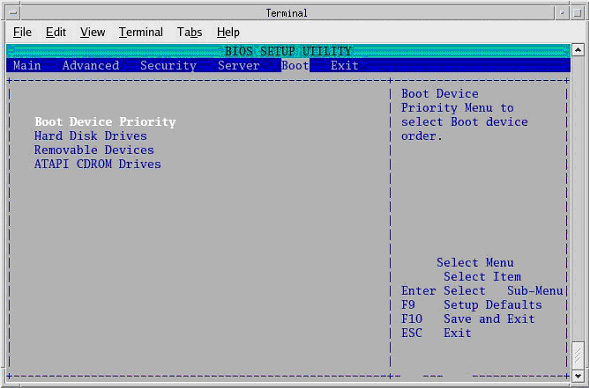
Select Boot Menu, using arrow keys.
-
Highlight Boot Device Priority Menu, then press Enter.
-
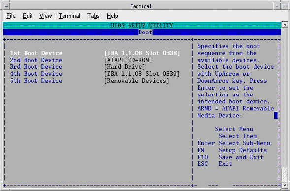
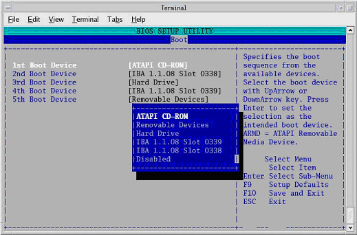
Highlight 1st Boot Device, then press Enter.
-
A small window will appear with the options available. Using the down-arrow key, scroll down to highlight IBA 1.1.08 Slot 0338, then press Enter.
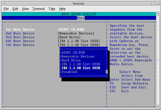
-
Using the down-arrow key, scroll down to highlight the 2nd Boot Device entry. Press Enter.
-
A small window will appear with the options available. Using the down-arrow key, scroll down to highlight the ATAPI CD-ROM entry. Press Enter.
-
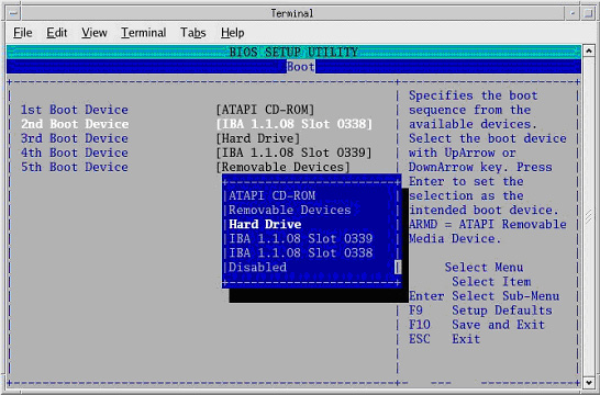
Using the down-arrow key, scroll down to highlight the 3rd Boot Device entry. Press Enter.
-
A small window will appear with the options available. Using the down-arrow key, scroll down to highlight the Hard Drive entry. Press Enter.
-
Verify the Boot device Priority is set to:
IBA 1.1.08 Slot 0338
ATAPI CD-ROM
Hard Drive
IBA 1.1.08 Slot 0339
Removable Devices
note:The removable devices might not be present. This is OK.
-
Press Esc to exit back to Boot menu.
-
Save DARC BIOS settings:
-
From Boot menu, arrow to (move to) Exit menu.
-
Highlight Exit Saving Changes, and press Enter
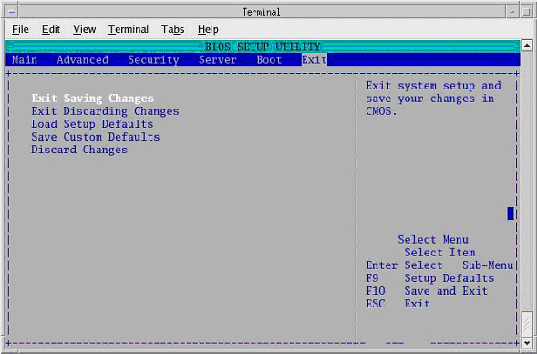
-
Highlight [Yes], and press Enter, to “Save configuration changes and exit now.”
Wait one minute.
note:After saving the DARC BIOS, the DARC BIOS Setup Utility will disappear (within one minute) and the DARC will begin to Reboot. If the BIOS SETUP UTILITY window does not disappear within a minute, perform the steps within this section again.
-
-
When the darc login: prompt appears, close the Terminal Window.
3.6.6 Delete SCSI Partitions on the DARC Node
This process is performed with Applications down.
If the Host Computer is able to successfully remote shell the DARC Node, perform the instructions in this section. Performing the reconfigScanDisk script may cause DARC Node OS load issues. Deleting DARC Node SCSI partitions will prevent DARC Node OS load issues. The reconfigScanDisk script is not a viable/usable script on 06MW03.5 software/hardware and will be removed later in the LFC.
If unable to perform either a remote shell to the DARC (rsh darc) or the SCSI Partitions Delete process, continue with the next sub-section, “LFC - OS Installation on DARC from Host”.
In a Unix Shell, type the following:
-
{ctuser@hostname} su -
-
password: <password>
-
[root@hostname] rsh darc
-
[root@darc] umount /raw_data
note:Some previous DARC Application Software versions may not have mounted /raw_data. In this case, you will see “umount: /raw_data: not mounted” message.
-
[root@darc] parted -s /dev/sda rm 1
The command contains the number “one”, not the letter “l”.
note:Normally, there will be no output or message displayed after performing the parted commands.
However, should the following message appear, ignore it and continue.
Warning: Unable to align partition properly. This probably means that another partitioning tool generated an incorrect partition table, because it didn't have the correct BIOS geometry. It is safe to ignore, but ignoring may cause (fixable) problems with some boot loaders.
-
[root@darc] parted -s /dev/sdb rm 1
-
Close the Unix Shell.
3.6.7 OS Installation on DARC from Host Computer
The OS DVD will be used again; however, this time it will be loaded onto the DARC Node from the Host Computer. If any problems arise, verify the correct disk is installed.
The DARC OS is loaded from the Host Computer DVD-ROM Drive.
-
Place OS DVD into the Host Computer DVD-ROM Drive. (See Illustration, below.)
-
Open a Unix Shell and type the following:
-
{ctuser@hostname} su -
-
Password: <password>
-
[root@hostname] cd /usr/g/scripts
-
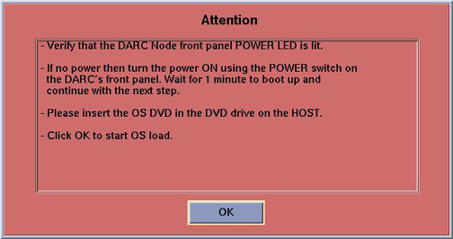
[root@hostname] ./start_darcOS
An Attention window appears. See the illustration below.
-
-
Follow the instructions in the Attention window and then insert the Linux Operating System, version 4.3.16 DVD into the Host Computer DVD-ROM Drive.
-
Select OK.
A sh window displays initial information, followed by a series of four rows of dots.
sh
Copying OS packages from the DVD to the HOST’s hard drive. This takes about 10 minutes.………………………………………………………………………….
………………………………………………………………………….
………………………………………………………………………….
………………………………………………………………………….
note:The display of dots reflects the copy process from the Host Computer DVD drive to the DARC Node. This process takes approximately 15 minutes.
-
Once the copy process is complete, the load will begin and the following message will appear:
OS load has started. This takes about 18 minutes.
##.## % done.
note:The DARC OS Load will stop prematurely ONLY if an error is encountered. An Error Dialog Box will appear with a brief description of the error. Select OK after reading the instructions displayed on the Monitor. Refer to DARC OS Load Pop-Up Boxes for additional information on these error pop-up windows. Also, if any problems arise, verify the correct software disk is installed and verify BIOS Setup Utility Boot Order is correct.
note:A %done status is displayed during the DARC OS load. This is only a timed countdown sequence and does not provide status of the actual load process. When the DARC OS load has completed a reboot message will appear.
-
Once the load process is complete, a sh window appears and the DARC reboots:
Sh
Waiting for the DARC to boot up…
-
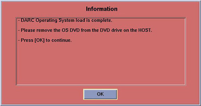
When the DARC OS load has completed, a pop-up message is displayed:
-
The OS disk ejects automatically. Remove the OS disk from the drive and close the drive.
-
Select OK.
-
To verify the OS has been loaded on the DARC Node, open a Unix Shell and type the following:
note:If the DARC login prompt [root@localhost root] is not present, then try reloading the DARC Node OS again per the procedure. Always be sure the DARC OS matches the Host OS already loaded.
-
{ctuser@hostname} su -
-
Password: <password>
-
[root@hostname] rsh darc
-
[root@localhost root]
(If the prompt is displayed exactly as shown, then the login was successful and the DARC OS was loaded properly.)
-
[root@localhost root] exit
-
-
This completes the OS load on the DARC.
-
Next: load the DARC Applications in the HP Host Computer. See DARC Application Software Installation from Host Computer.
3.6.8 DARC Application Software Installation from Host Computer
The DARC Applications have already been loaded on the Host Computer during the CT Applications load process. As a result you no longer need to reinsert the Application disk into the Host Computer.
-
Open a Unix Shell and type the following:
-
{ctuser@hostname} su -
-
Password: <password>
-
[root@hostname] cd /usr/g/scripts
-
[root@hostname] ./start_darc_load
A shell window pops up and the load begins. A successful load takes 5-12 minutes.
When the process is complete the load window will disappear.
-
-
Close the Unix Shell (do not use for the next process).
3.6.9 Remove 'reconfigScanDisk' Script
Overview: The reconfigScanDisk script is not used and must be removed with each LFC. The new script to verify the Disk Array in the SDDA or DARC 2 Node is {ctuser@darc} sudo gre-raid. This script is performed with the option to repartition or create (-c), assemble (-a) or query (-q).
Open a Unix Shell and type the following:
-
{ctuser@hostname} su -
-
Password: <password>
-
[root@hostname] rsh darc
-
[root@darc] cd /usr/g/scripts
-
[root@darc]] ls reconfigScanDisk
reconfigScanDisk
-
[root@darc] rm reconfigScanDisk
Type y to remove: y
-
[root@darc] ls reconfigScanDisk
reconfigScanDisk will be gone.
Close the Unix Shell.
3.6.10 Return DARC BIOS to Original Settings
This section describes the steps necessary to change the BIOS on the DARC Node. This step is required to return the DARC BIOS to its original settings, now that the OS has been loaded onto the DARC from the Host Computer. The DARC BIOS was changed at the beginning of the procedure to load the OS onto DARC from the Host Computer, and now will be changed back for normal operation.
The DARC BIOS must be returned to their original settings to avoid a known Intel PXE boot problem, which will prevent future communication to the DARC Node.
Be patient. Telnet response may be slow.
-
Open a Unix Shell and type the following:
-
{ctuser@hostname} su -
-
Password: <password>
-
[root@hostname] service cliservice start
-
[root@hostname] telnet localhost 623
-
server: darc
-
username Enter
-
password Enter
Login successful
-
dpccli> reset -c
ok
GEHC/CTT Linux 4.3.16
Kernel 2.6.7-2.2 smp...
See you on the darc side of the moon
darc login:
note:A slight delay here is normal. Be patient.
-
-
Interrupt the DARC boot process to enter the BIOS Setup mode. When the message “Press <F2> to enter setup” appears, press F2.
note:F2 may have to be pressed many times before BIOS setting screen can be seen.
There will be a short delay before the DARC BIOS setup screen is displayed.
-
Highlight Boot Menu, using arrow keys.
-
Highlight Boot Device Priority Menu, then press Enter
-
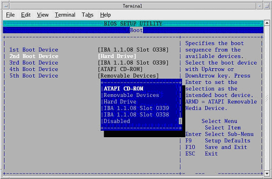
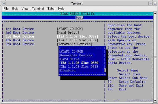
Highlight 1st Boot Device, and press Enter.
-
Continue setting Boot Device Priority.
-
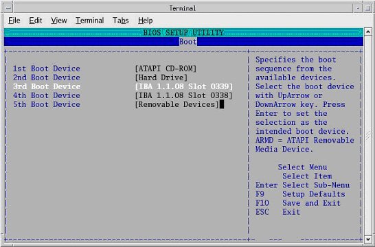
Verify the Boot device Priority is set to:
ATAPI CD-ROM
Hard Drive
IBA 1.1.08 Slot 0339
IBA 1.1.08 Slot 0338
-
Press Esc to exit back to Boot menu.
-
Save BIOS settings:
-
From Boot menu, arrow to (move to) Exit menu.
-
Highlight Exit Saving Changes, and press Enter.
-
Highlight Yes, and press Enter, to “Save configuration changes and exit now.”
Wait one minute.
note:After saving the DARC BIOS, the DARC BIOS Setup Utility will disappear (within one minute) and the DARC will begin to Reboot. If the BIOS SETUP UTILITY window does not disappear within a minute, perform the steps within this section again.
-
-
When the darc login: prompt appears, close the Terminal Window.
3.7 Confirm DARC Software Has Loaded
Verify the OS and Application Software has loaded correctly.
-
Open a Unix Shell and type the following:
-
{ctuser@hostname} rsh darc
-
[ctuser@darc] cd /usr/g/bin
-
[ctuser@darc bin] ./swhwinfo
-
[ctuser@darc bin] cat /GEHC*
-
-
Confirm that the swhwinfo results match the software revision shown on the Applications disk.
06MW03.5. <hardware revision info here>
Example: 06MW03.5.H2_P_S4_G_Zeus
-
If the revisions match, continue with this procedure.
-
If the revisions do NOT match, reload the software (Load from Cold Installation Procedures).
-
-
Verify that cat results match the Operating System version and Software Build Date.
Release: GEHC/CTT Linux 4.3.16
Built: Tue Jul 12 12:29:10 CTD 2005
-
Close the Unix Shell.
3.8 Set Time and Date
You must set the date and time on the Host Computer with Application Software down.
-
Open a Unix Shell and log in as root:
-
{ctuser@hostname} su -
-
Password: <password>
-
-
Set date and time. Type the following:
{root@hostname}# setdate to be prompted through the individual entries. Where:
Enter the current Year or "q" to quit (1980-2030) [2006]:
Enter the current Month or "q" to quit (1-12) [04]:
Enter the current Day or "q" to quit (1-30) [14]:
Enter the current Hour (Military Time) or "q" to quit (0-23) [18]: 15
Enter the current Minute or "q" to quit (0-59) [13]: 18
\nUpdating the time on the OC and SBC, Please Wait...
PING darc (172.16.0.2) 56(84) bytes of data.
-
Upon completing either of the above commands, the user will receive one of the two following responses:
-
If the DARC Node has been replaced and has no software, the following response will appear:
--- darc ping statistics ---
1 packets transmitted, 0 received, 100% packet loss, time 0ms
The darc is not responding. darc will sync time with oc during next darc reboot
Current OC date : Fri Apr 14 15:18:00 CDT 2006
Could not retrieve the SBC TImeZone.
Please make sure the TimeZones for the OC and SBC are the same.
[root@hostname]#
-
If the DARC Node is being reloaded and had software, the following response will appear:
--- darc ping statistics ---
1 packets transmitted, 1 received, 0% packet loss, time 0ms
rtt min/avg/max/mdev = 0.139/0.139/0.139/0.000 ms, pipe 2
connect to address 10.0.1.2: Connection refused
connect to address 10.0.1.2: Connection refused
trying normal rsh (/usr/bin/rsh)
connect to address 10.0.1.2: Connection refused
connect to address 10.0.1.2: Connection refused
trying normal rsh (/usr/bin/rsh)
Current OC date : Fri Apr 14 16:14:05 CDT 2006
Current DARC date : Fri Apr 14 16:14:04 CDT 2006
setdate completed with NO ERRORS.
[root@hostname]#
-
-
Close the Unix Shell.
3.9 Reboot the Operator Console & Stop Application from Starting Up
-
Open a Unix Shell and type the following:
-
{ctuser@hostname} sync
-
{ctuser@hostname} sync
-
{ctuser@hostname} reboot
A message appears: The system is going down for reboot NOW!
-
-
After approximately 4-5 minutes a pink pop-up window appears with the message:
CT Software Auto-Start Disabled.
-
Select OK.
3.10 Start Up the CT Applications
-
When the Host Computer is up, open a Unix shell and type the following:
{ctuser@hostname} st
-
A pink pop-up Attention Message appears: OC initializing. Please wait….
note:If a message concerning incorrect DAS configuration is encountered, review the Error Log for the Card List issue. Select from the following two methods to alleviate this issue: Flash Download Update or Power OFF the Axial Drive and HVDC at the Gantry service panel - turn OFF DAS Power for 1 minute - turn DAS Power back ON - turn Axial Drive and HVDC at the Gantry service panel back ON - Flash Download Update - verify error message has disappeared. If error message reappears then troubleshoot the DAS/DCB.
-
Select OK for other pink message boxes that appear throughout the reboot process.
After each reboot during the software load process, an 'Unrecognized X-Ray Tube' message will be displayed (as shown below) until the tube identity has been selected (later in this procedure) and 'Flash Download' has also been performed.
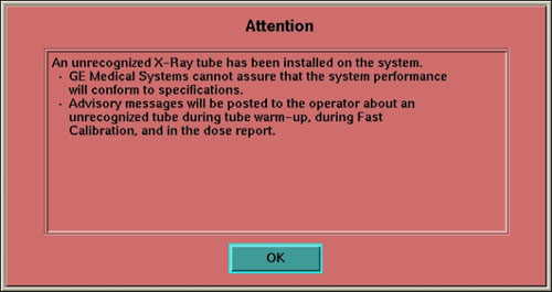
-
If any Recon Selftest Failures are encountered, review the error log. Make certain to note the errors for troubleshooting after the LFC.
3.11 Restore System State
Systems upgrading from software 04MW44.9 or previous versions will need to re-enter the HIPAA configuration data recorded earlier. The new system uses a different mechanism and the previously saved files do not work with 05MW14.5 or later software versions.
3.11.1 IRIX Restore System State from MOD, for GOC1 Upgrades Only
This procedure is ONLY for upgrade sites with System State Information on a MOD (not a DVD). All other sites should restore system state as instructed in Restore System State from DVD (GOC2/GOC3/GOC4).
-
When applications are up, open a Unix Shell from the Service icon -> Utilities tab -> Utilities folder. Perform the following:
-
Insert the IRIX System State MOD into the SCSI Tower MOD drive. The DVD drive should be empty.
-
{ctuser@hostname} cd /usr/g/bin
-
{ctuser@hostname} sysstategui -MOD -IRX2LNX
-
When the system state GUI comes up, select and restore each item individually, by selecting the item and then selecting RESTORE.
note:Continue until all items are restored.
-
The IRIX to Linux conversion should take around 40 minutes. The command lines will scroll very quickly during the conversion in the window. When the scrolling stops, the System State has completed the conversion. When it has completed, close the window.
-
-
Shutdown Applications.
-
Close the Unix shell.
-
Remove the MOD from the drive.
-
Proceed toRun Tube Usage Conversion Tool (skip the next sub-section, “Restore System State from DVD”).
3.11.2 Restore System State from DVD (GOC2/GOC3/GOC4)
-
Open a Unix Shell and verify the SCSI Tower MOD and DVD are present:
{ctuser@hostname} scsistat
-
Close the Unix Shell.
-
Insert the Save System State DVD into DVD-RAM SCSI Tower drive.
-
Select the SERVICE icon.
-
Select: UTILITIES
-
Select: SYSTEM STATE
-
Select ALL
-
Select RESTORE
-
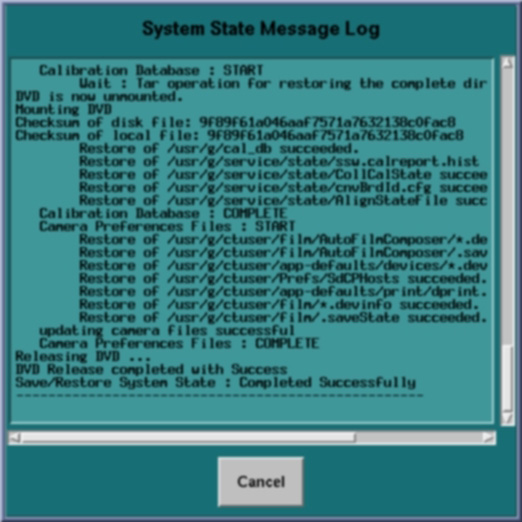
Verify the overall system state content has restored correctly (look for message “Save/Restore System State Completed Successfully”), then select CANCEL.
-
When completed, select DISMISS or close the window.
note:If Scan Hardware Reset question appears - answer [NO]. This reset is performed during FLASH Download Update.
3.12 Run Tube Usage Conversion Tool
If reloading 06MW3.5, skip this section (go to Install IIP Small Font Correction SW for Common Service Desktop).
This tool is to be run only once.
The Tube Usage File information is critical. It captures required Tube Warranty and Performance Information.
-
Shut down Applications using the following commands (Do NOT use Pink Shutdown Button):
-
Select the Common Service Desktop (CSD)
-
Select Utilities
-
Select Applications Shutdown
-
-
Confirm Applications shut-down by selecting OK.
-
Open a Unix Shell and type the following:
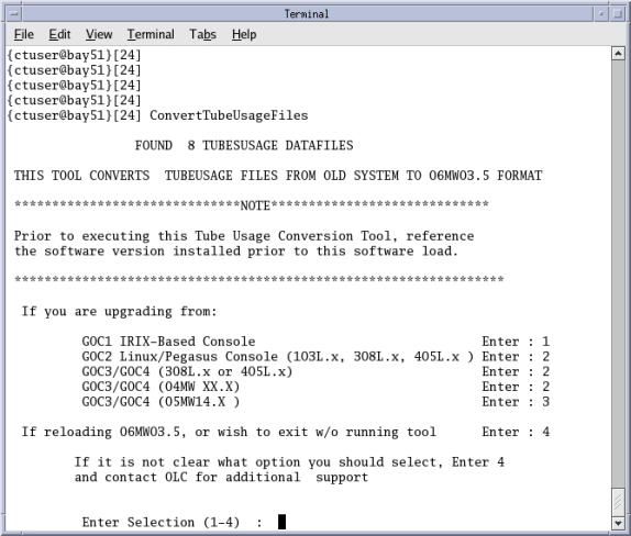
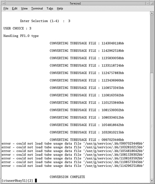
{ctuser@hostname} ConvertTubeUsageFiles
-
A screen will appear as follows:
-
Select the upgrade type and enter the appropriate number in the selection field and press Enter.
-
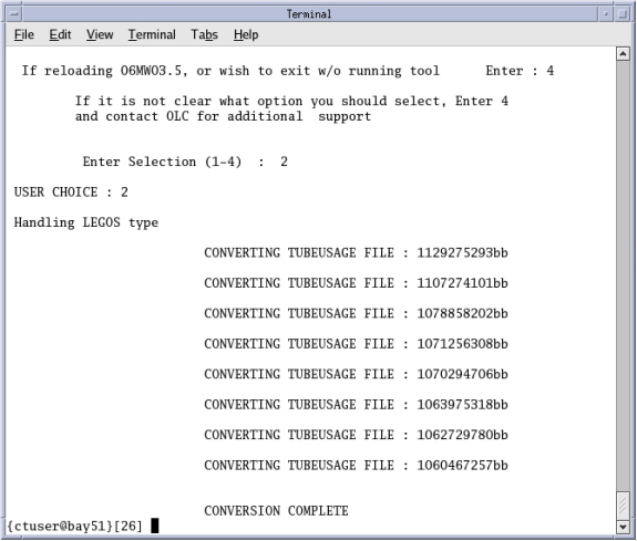
The output will look similar to the following for a successful conversion. There should be one conversion message per Tube Usage File Converted.
 note:
note:If you get a screen with errors as shown in the following example, call the OLC for Tube Usage Conversion Support.
-
Restart Applications by opening a Unix Shell and typing the following:
-
{ctuser@hostname} sync
-
{ctuser@hostname} sync
-
{ctuser@hostname} reboot
-
-
After the system reboots, open a Unix Shell and type the following:
-
{ctuser@hostname} cd ~service/.bb_BAK
(note, there is no space between “/” and “.bb”)
-
{ctuser@hostname} ls
Count the number of files and record the number.
-
-
Confirm Tube Usage Conversion was successful:
-
Open the Common Service Desktop.
-
Select ErrorLogs
-
Select Tube Usage
-
Count the number of tubes listed. If the number of files on the CSD do not match the number recorded in step 9 above, contact the OLC (or you GE Sales Representative) for Tube Usage Conversion Support.
-
Select Summary for each of the Tubes
-
View the entire file(s), checking for the following:
-
Is header information readable?
-
Are Tube mAs readings within the range of 10,000 – 200,000,000?
-
Do Tube mAs readings match the readings recorded in Save State section earlier in LFC procedure?
-
-
If any part of step “f” fails, call the Online Center (or you GE Sales Representative) for Expert Tube Usage Conversion support.
-
-
If your verification passes, then continue with the next section.
3.13 Install IIP Small Font Correction SW for Common Service Desktop
-
Open a Unix Shell and type the following:
-
{ctuser@hostname} su -
-
Password: <password>
-
[root@hostname] cd /usr/g/ctuser/insite/patches
-
[root@hostname] tar -xf iip_3.3.7_ct_restore_patch.tar
-
[root@hostname] ./post_pathfinder1.5_restore.sh
-
-
Close the Unix Shell.
3.14 Retro Recon Test
The Reconstruction (not Scan) portion of the system can be tested at this point.
When Application Software is up, perform the following:
-
Select Recon Management, and select Restart Queue if not in the Idle Mode.
-
Select RETRO RECON on the left Monitor.
-
Select the rat gold series.
-
Select SELECT SERIES.
-
Select CONFIRM.
-
Verify the image(s) reconstruct and are displayed.
-
Select QUIT.
3.15 Recon Self-Test
-
Select the Service Icon.
-
Select Diagnostics.
-
Under Image Generation, select Recon Data Path.
-
Select Recon Data Path.
-
Verify it is set to 1 and ALL.
-
Select Run.
-
Verify Recon Data Path tests pass.
-
Select Dismiss or close the GUI.
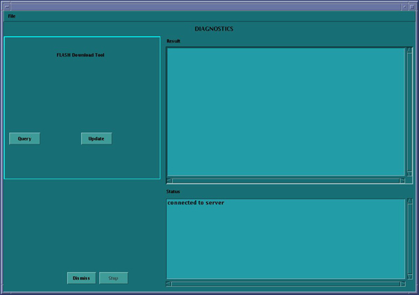
3.16 FLASH Download
-
Select the SERVICE DESKTOP.
-
Select in sequence: .
-
Select UPDATE. Ignore any initial errors.
-
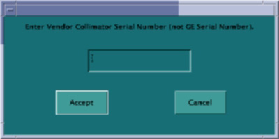
When the pop-up shown below appears, enter the Collimator Serial Number, and select Accept.
-
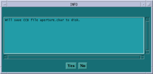
When the pop-up shown below appears, select Yes, to save the CCB file.
-
When then Flash Download process is complete, select DISMISS or close the window.
 note:
note:After Flash Download the system will report the following message:
The entire Generator database has been reset. You may now restore JEDI runtime parameters. Filament calibration is required before scanning patients.
If you are reloading software, this message may not appear. If you get this message, you must perform a Filament Calibration, because the JEDI database was reset.
-
If there are any issues with the install, verify the reset switch at the gantry is not flashing and reset the 120 VAC, if necessary. Also, try to ping the following (press Ctrl-C and close the shell when finished pinging):
(For LightSpeed 4.X)
-
ping obcr
-
ping etc
-
ping stc
(For LightSpeed 5.X Pro16 (100kW) and Pro16 (80kW))
-
ping orp
-
ping stc
- OR -
ping tgp
-
3.17 Install Software Options
|
|
-
Insert the Options DVD in the SCSI Tower DVD-RAM drive.
note:Options loaded via DVD or CD will NOT be saved to System State.
All Options loaded via e-License WILL be saved to System State.
-
With the Applications up, select the SERVICE DESKTOP.
-
Select CONFIGURATION.
-
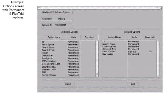
Select INSTALL OPTIONS. A blank Software Options screen appears:
-
Select INSTALL. A Select Mechanism window opens (see illustration, below). Select the mechanism through which you want to install Option Keys.
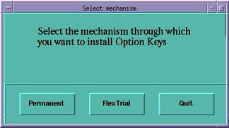
-
Select Permanent. A Select Device window opens (see illustration, below). Select the mechanism through which you want to install the Permanent Option Keys.
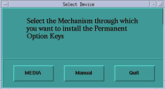
-
Select the MEDIA button and insert the Options DVD or MOD.
-
Select OK. Available options appear on the Software Options screen.
-
Select either the DMPR (Direct Multi Planar Reformat) or Variviewer Option installations, if applicable, per Note:
note:IMPORTANT!
DMPR and Variviewer are mutually exclusive options with 05MW14.5 or later software. If you have DMPR (the full option), software will not allow you to install Variviewer, and vice-versa. For example, do not install Variviewer, if you plan to load DMPR.
-
Perform the following Option installations, if applicable:
note:The order of installation is critical.
-
VolumeViewer
-
CardIQ
-
CardEP
-
Exam Split
-
-
Pick remaining options one at a time from the Available Options list and select INSTALL to update each selection and place it on the Installed Options List.
-
When the process is complete, select Quit then Quit to close the window.
3.18 ScanUsage File Work-Around
Do not perform this step if the previous SW was 05MW14.5 or more recent (e.g., 06MW3.5).
Open a Unix shell and type the following:
{ctuser@hostname} rm -rf /usr/g/service/ScanUsage
3.19 Edit Gantry Revolutions Information - IRIX Upgrades Only
If upgrading a GOC1 (IRIX) Console to a GRE/Xtream Console, then the gantry revolutions information must be restored.
-
Open a Unix shell and type the following:
{ctuser@hostname} getStats
-
Select menu option (by typing the appropriate number) to Update Gantry Revolutions Counter Stats.
-
Enter the gantry revolutions counter information captured at the beginning of this LFC (IRIX Systems Upgrading to Linux - Save System State).
3.20 Feature Installation
3.20.1 HIPAA
Systems upgrading from software 04MW44.9 or previous versions will need to re-enter the HIPAA configuration data recorded earlier. The new system uses a different mechanism and the previously saved files do not work with 05MW14.5 or later software versions.
If HIPAA is turned ON, then configure it now. (Refer to HIPAA Configuration) When HIPAA configuration is complete, return to this procedure.
3.20.2 Product Network Filters (PNF)
For general information on Product Network Filters, please see Product Network Filter Theory.
If your customer has special network requirements, then proceed to Configure Product Network Filters now. When PNF configuration is complete, return to this procedure.
If network problems arise after configuring PNF:
-
Turn OFF PNF.
-
If the problem still exists with PNF off, then troubleshoot the network.
-
If networking issues no longer exist, then call the OLC Connectivity Team to resolve the issue.
-
-
Once the PNF setup problem is fixed, turn PNF back ON.
3.20.3 AW Direct Connect
If the site requires the configuration of AW Direct Connect, then configure it now (see AW Direct Connect). When configuration is complete, return to this procedure.
3.21 Tube Identification
|
|
If the tube in your system has a ’Smart ID’ board, the software automatically selects the tube identity, and sets it to ‘GE Performix Tube’. There is no action needed. For all other systems or if the software does not automatically select the tube identity, follow the procedure shown in the Flowchart below.
Verification that a tube is a GE Healthcare tube (called “GE Performix Tube” in the TIC tool) can be done by checking the tube insert model number (2120785 or 2120785-2), which can be found on the tube rating plate. (Exception: The “Performix Pro” is a GE OEM tube, but does not have this tube insert model number.)
Do not double-click the Tube Certification Tool. This will cause more than one tool window to be displayed; one with message ‘service key information not available’. If this happens, close the window and try again. If this happens more than once, reboot system and try again.
Figure 4. Selection of Tube Identity
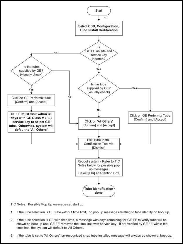
Flowchart Note:
Possible pop-up messages at start-up:
-
If the tube selection is GE tube without time limit, no pop-up messages relating to tube identity on boot up.
-
If the tube selection is GE with time limit, a message with days remaining for GE FE to verify tube will be shown on boot up until GE FE removes the time limit with service key. If not verified by GE FE within the time limit, the system will default to 'All Others'.
-
If the tube is set to 'All Others', unrecognized x-ray tube installed message will always be shown at boot up.
Please refer to Tube Install Certification Tool - Screens for examples of the screens displayed by the Tube Install Certification Tool.
3.22 FLASH Download
Overview: This is a firmware requirement to load tube identification parameters.
-
Select the SERVICE icon.
-
Select in sequence: .
-
Select UPDATE. Ignore any initial errors.
-
When then Flash Download process is complete, select DISMISS or close the window.
-
If there are any issues with the install, verify the reset switch at the gantry is not flashing and reset the 120 VAC, if necessary. Also, try to ping the following (press < Ctrl-C> and close the shell when finished pinging):
(For LightSpeed 4.X)
-
ping obcr
-
ping etc
-
ping stc
(For LightSpeed 5.X Pro16)
-
ping orp
-
ping stc -OR- ping tgp
-
3.23 Restart the System
3.23.1 Restarting the System
|
|
To restart the system:
-
Replace the Hospital Backbone Ethernet cable to the Console Bulkhead Assembly (located at the rear of the Operator Console).
-
Open a Unix shell and type the following:
{ctuser@hostname} reboot
3.23.2 If HIPAA Present set to ON - Admin Screen
When the system comes up the following screen will be displayed if HIPAA Present was set to On during the LOAD process. Verify the admin screen below has the following 'Select user':
-
Select user: admin
-
Password: ctAdmin
3.24 System Sanity - Scanning & Network Operation
-
Successfully perform a Scout scan.
-
Successfully perform a Helical scan.
-
Successfully perform an Axial scan.
-
If have DICOM print configured, perform DICOM print to confirm network operation (Product Network Filter (PNF) setup).
-
If have archive server configured, perform image archive & retrieve to confirm network operation (PNF setup).
Software Load Process is now complete.
3.25 Finalization
-
Perform FastCal as required.
-
Remove the System State DVD-RAM from the SCSI Tower.
-
Replace the front and rear Operator Console covers.
-
(For FX/Xtream w/Q1 '06 SW Upgrades Only) Return to the Flowchart/Steering Guide to complete the installation.
-
Save System State:
-
Insert the Save System State DVD into the DVD tower drive.
-
Select: SERVICE DESKTOP
-
If reloading software, select: UTILITIES
-
Select: SYSTEM STATE
-
Select ALL to select all the cals, characterizations, etc.
-
Select SAVE.
-
If applicable, select OK when the following message appears: System State Media Status: Please insert a DVD or MOD into the drive and press Save again.
-
When completed select DISMISS.
-
Save all reformat / recon protocols.
-
Close the Service Desktop window in the upper left corner of the screen.
-
Sites performing the next sub-section should not remove the DVD from the SCSI Tower DVD-RAM drive.
-